Heat dissipation structure of high-power light-emitting diode (LED) illuminating lamp

A technology of LED lighting and heat dissipation structure, which is applied in the field of electronics, can solve the problems of unsuitable high-power LED heat dissipation and development, poor compatibility of LED radiators, small contact heat transfer area, etc., to achieve lower temperature, compact structure, and meet heat dissipation requirements. Effect

Inactive Publication Date: 2011-04-06
BEIJING UNIV OF CHEM TECH +1
View PDF10 Cites 5 Cited by
  • Summary
  • Abstract
  • Description
  • Claims
  • Application Information

AI Technical Summary

Problems solved by technology

[0004] In order to solve the problems of small contact heat transfer area between the traditional LED heat dissipation substrate and the heat sink, low heat dissipation efficiency, large thermal resistance, poor compatibility with the LED heat sink, high replacement cost when damaged and unsuitable for heat dissipation and development of high-power LEDs, the present invention Provide a combined LED radiator structure

Method used


Image

  • Heat dissipation structure of high-power light-emitting diode (LED) illuminating lamp
  • Heat dissipation structure of high-power light-emitting diode (LED) illuminating lamp
  • Heat dissipation structure of high-power light-emitting diode (LED) illuminating lamp

Examples


Embodiment Construction

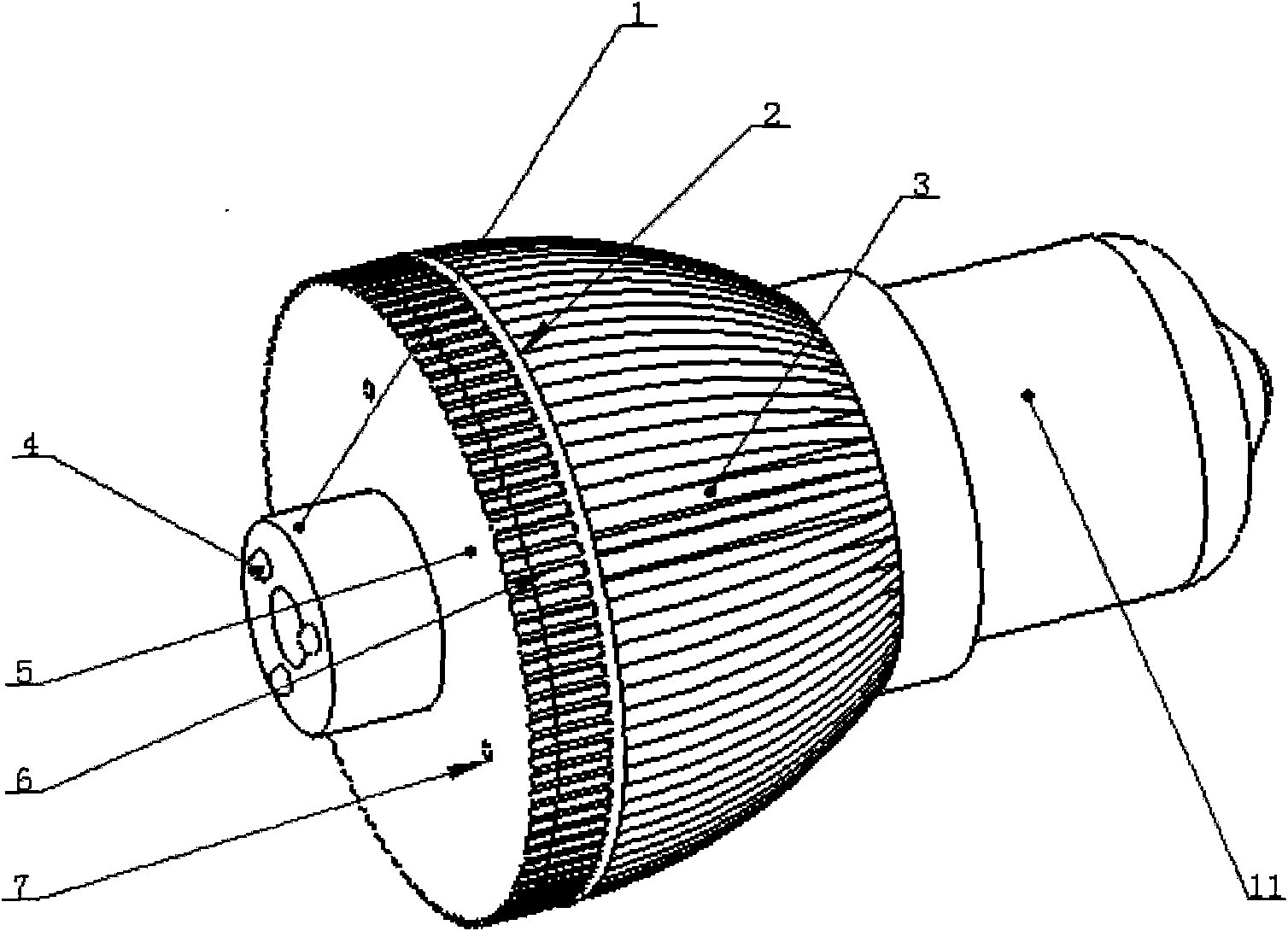
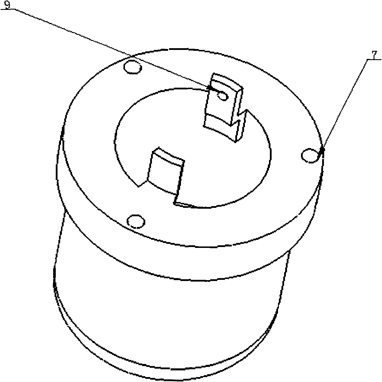
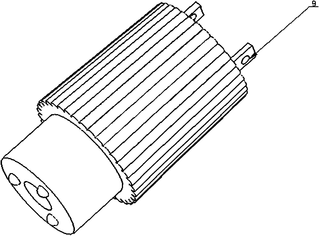
[0020] Depend on Figure 1-Figure 5 As shown, the present invention includes LED chip base column 1, heat dissipation shell 2, fixed gasket 5 and screw socket 11. In order to quickly reduce the temperature of high-power LED 4, LED chip base column 1 needs to be inserted into heat dissipation shell 2, and The contact curved surface has a wavy surface, and it is filled with a thermally conductive adhesive material, such as thermally conductive silica gel, so that it is in close contact with the inner surface of the heat dissipation shell 2, and a high-power LED4 is fixed on the front end surface of the cylindrical LED chip base column 1 , the chip base and the heat dissipation shell are made of a heat conductor.

[0021] The heat conductor is: aluminum, copper or a non-metallic material with high heat conduction efficiency that meets heat dissipation requirements. Because the power of the high-power LED 4 is different, its calorific value is also different, so one of the above-...


PUM


Abstract

The invention discloses a heat dissipation structure of a high-power light-emitting diode (LED) illuminating lamp, which belongs to the technical field of electrons. The heat dissipation structure comprises a cylindrical LED chip base-column, a heat dissipation shell, a retaining washer and a screw opening, wherein the external surface of the heat dissipation shell is provided with a micro-slot structure; the heat dissipation shell is sleeved outside the cylindrical LED chip base-column; the retaining washer is sleeved on the front end of the chip base-column, and connected with the heat dissipation shell by bolts; the screw opening is connected and fixed with the heat dissipation shell by the bolts, and connected with the chip base-column by contact points; the external surface of the rear part of the chip base-column is provided with a cylindrical contact curved surface which is fitted with the heat dissipation shell, and the heat dissipation shell is provided with fins. By using the heat dissipation structure of the invention, the heats gathered on the chip part can be quickly reduced, thereby minimizing the temperature of the high-power LED lamp; and because the chip base-column is detachable, when the LED chips reach the usage life-spans thereof or are damaged because of other reasons, the whole LED lamp is not required to be replaced but just replacing the chip base-column.

Description

technical field [0001] The invention relates to an electronic heat dissipation structure, in particular to a combined LED lamp radiator, which belongs to the technical field of electronics. Background technique [0002] Light-emitting diode (LED), also known as semiconductor lamp, is a light-emitting device that can directly convert electrical energy into light energy and output it. It is a cold light source without filament. LED is known as a new generation of energy-saving light source that can replace traditional light sources. In addition to the advantages of saving energy, LED also has the characteristics of long life, small size, safety and reliability, environmental protection and pollution-free, multi-purpose, and easy control. LED has a wide range of uses and can replace traditional light sources in many occasions. When high-power LED lighting fixtures appear, the speed at which they replace traditional light sources has been accelerated, and it has also made it po...

Claims


Application Information

Patent Timeline
Patent Type & Authority Applications(China)
IPC IPC(8): F21V17/12F21V19/00F21V29/00F21Y101/02F21V29/74F21V29/85
Inventor 张亚军庄俭吴大鸣韩月
Owner BEIJING UNIV OF CHEM TECH
Why Eureka
Try Eureka