Hierarchical cavity type solar heat absorber and heat exchange system

A technology of solar heat absorber and heat exchange system, which is applied in the direction of solar thermal power generation, solar thermal devices, and mechanical power generated by solar energy, etc., which can solve the problems of excessive heat flux design, limit wall thickness, and reduce unit efficiency, etc., to achieve Prolong the effective working time, increase the pressure level of the working medium, and reduce the effect of heat radiation loss

Active Publication Date: 2012-03-14
DONGFANG BOILER GROUP OF DONGFANG ELECTRIC CORP
View PDF2 Cites 0 Cited by
  • Summary
  • Abstract
  • Description
  • Claims
  • Application Information

AI Technical Summary

Problems solved by technology

[0003] Due to the uncontrollable characteristics of sunlight and the limitation of existing heat collector technology, the heat absorber in the existing solar power generation circuit often operates in a large range of radiation fluctuations. If the heat absorber is not properly designed, There are many problems in the efficiency and safety of the power station; the main manifestations are: ①. The heat energy of all collectors is concentrated in a small range, and the heat flux density in the cavity is too large, so the heat absorber must have a strong heat exchange ②, the temperature in the cavity is too high, which increases the heat loss of the light boiler; ③, in order to ensure the safety of the heating surface in the high temperature cavity, the heat exchange capacity of the metal tube must be increased, which limits the heat exchange tube The wall thickness of the boiler limits the increase of boiler pressure parameters and reduces the efficiency of the unit; ④ Excessive heat flux design will seriously threaten the safety of the heat sink when the system fails

Method used


Image

  • Hierarchical cavity type solar heat absorber and heat exchange system
  • Hierarchical cavity type solar heat absorber and heat exchange system

Examples


Embodiment Construction

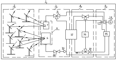
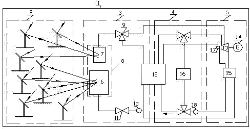
[0017] Such as figure 1 Shown is a specific embodiment 1 of the present invention, a solar thermal power plant 1 according to the present invention. Here, the solar thermal power plant 1 is composed of a solar concentrating field 2 , a solar steam circuit 3 , a fossil fuel steam circuit 4 and a conventional power generation system 5 . In this power generation circuit, there are a plurality of solar reflector concentrating fields 2 and a plurality of solar heat absorbers 8, and the heat absorbers of the solar heat absorbers 8 include independent first-stage heat absorbers 6 and second-stage heat absorbers 7, that is, the first-stage heat absorber 6 arranged with an evaporation heating surface and the second-stage heat absorber 7 arranged with an overheating heating surface, and the evaporation heating surface and the overheating heating surface are connected by a steam drum. The evaporating heating surface heats the feed water to generate saturated steam, and sends the satura...


PUM


Abstract

The invention discloses a hierarchical cavity type solar heat absorber which comprises a solar reflector and heat absorbers, and is characterized in that the heat absorbers comprise an independent primary heat absorber and an independent secondary heat absorber, namely a primary heat absorber with an evaporation heating surface and a secondary heat absorber with an overheating heating surface, wherein the evaporation heating surface and the overheating heating surface are connected through a steam pocket. The invention has the beneficial effects that as condensers and the heat absorbers are arranged in a targeted manner, the heat-flow density can be effectively distributed, the safety of the heat absorbers is ensured and the operation difficulty is reduced; the tube wall thickness of the heat absorbers can be properly increased so as to improve the pressure rating of a working medium and the unit efficiency; and the condensers are arranged in groups and the heat-flow density of each part in a heat receiver is controlled within a reasonable range so that temperature near the heat receiver can be reduced and the solar heat radiation loss after focusing is reduced.

Description

technical field [0001] The invention relates to a device for targetedly improving the efficiency and safety of a solar thermal power plant, in particular to a solar heat absorber used in a solar thermal power plant. Background technique [0002] Solar thermal power plants use numerous mirrors to focus solar radiation energy, and then use the focused radiation energy to heat the medium to generate electricity. This kind of thermal power station can exist independently from the solar power generation circuit, and can also form a thermal power station together with the water-steam power generation circuit using fossil fuels. The solar power generation circuit is composed of different types of concentrators, heat sinks and heat exchangers. The fossil fuel water-steam power generation circuit consists of an oil / gas boiler and a heat exchanger. Here, the solar power generation circuit is composed of many concentrators that focus the sun's rays on the heat absorber located in the...

Claims


Application Information

Patent Timeline
Patent Type & Authority Patents(China)
IPC IPC(8): F22B1/00F24J2/00F03G6/06F01D15/10
CPCY02E10/46
Inventor 奚正稳冉燊铭王军倪健邹军李由丁路覃小刚
Owner DONGFANG BOILER GROUP OF DONGFANG ELECTRIC CORP
Why Eureka
Try Eureka