

Omnibearing multi-duct energy-saving hot blast producing furnace
A hot air generator and multi-air duct technology, applied in heating devices, air heaters, fluid heaters, etc., can solve the problems of short combustion fire path, large furnace space, large energy consumption, etc., and achieve high heat energy recovery and utilization rate , The effect of the large heating area of the air duct and the reasonable structure of the air duct
- Summary
- Abstract
- Description
- Claims
- Application Information
AI Technical Summary
Problems solved by technology
Method used
Image

Examples
Embodiment Construction
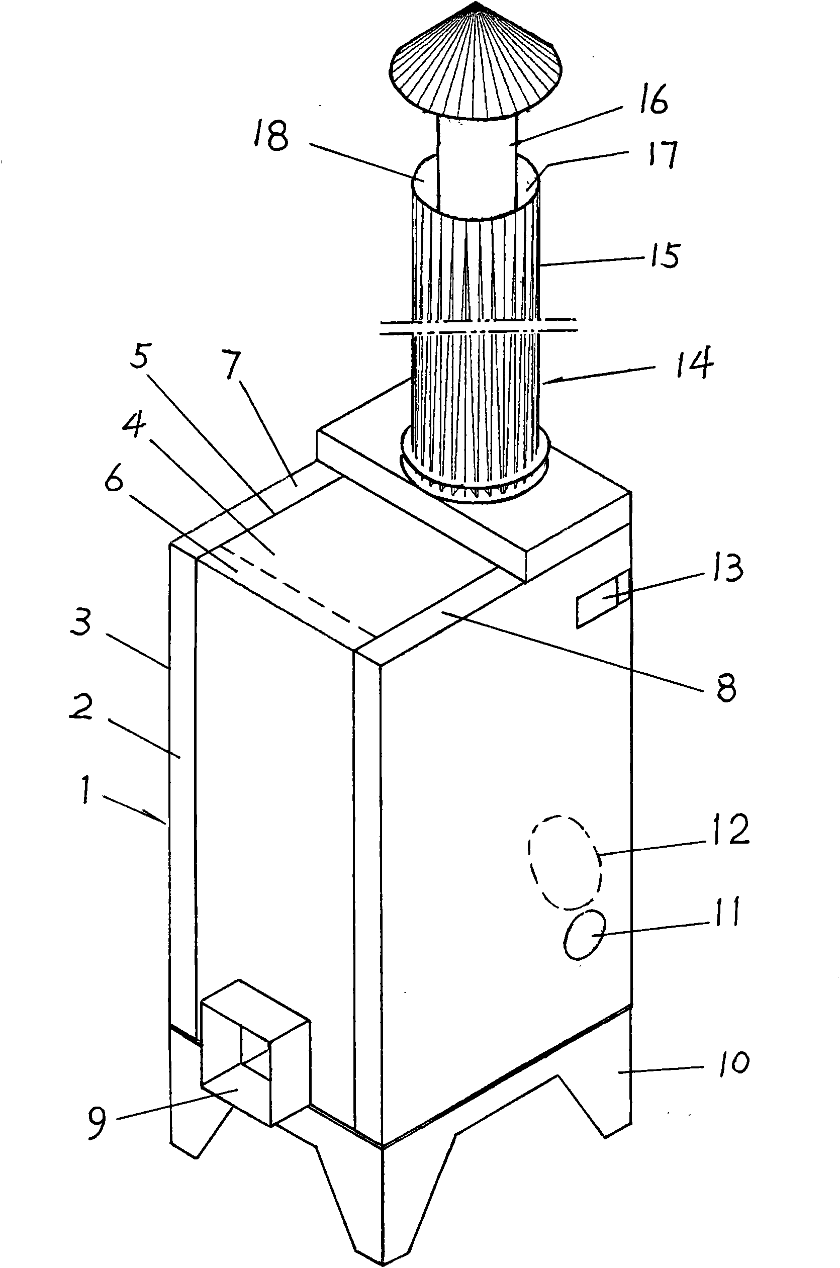
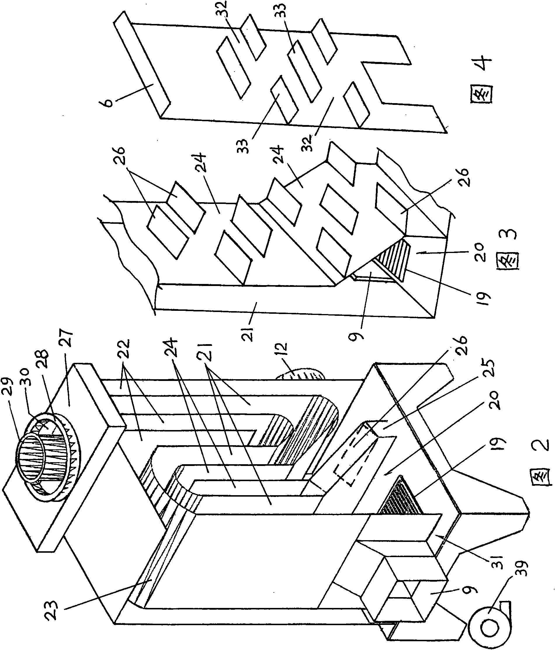
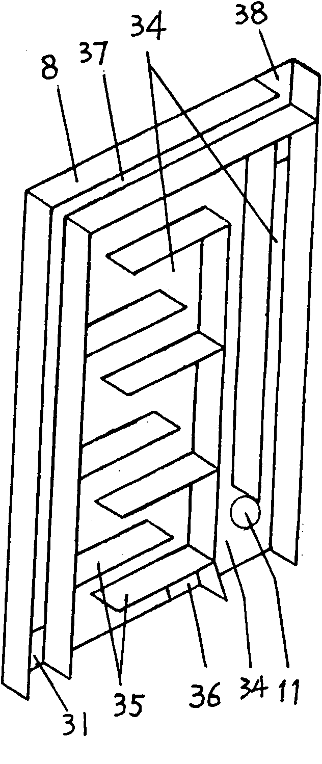
[0026]With reference to the accompanying drawings, it can be seen that the overall structure of this all-round multi-channel energy-saving hot blast generator of the present invention is composed of the following components: 1--furnace body, 2--outer furnace body (also known as the attached furnace body part), 3 -- the outer furnace wall of the outer furnace body (also known as the attached furnace wall), 4 -- the inner furnace body (also known as the main furnace body part), 5 -- the inner furnace wall of the inner furnace body (also known as the main furnace wall), 6--Front chamber (forming the heat-absorbing air passage of the front chamber), 7--Left chamber (forming the heat-absorbing air passage of the left chamber), 8--Right chamber (forming the heat-absorbing air passage of the right chamber), 9 --Stove mouth (stove burner mouth), 10--furnace base, 11-side chamber dust removal port located at the bottom of the serpentine fire path, 12-hot air outlet, 13-side chamber air ...
PUM
 Abstract
Description
Claims
Application Information