Three-frequency Koch fractal ring mirror image dipole antenna

A dipole antenna and dipole technology are applied in the field of three-frequency Koch fractal ring mirror dipole antennas to achieve the effects of large bandwidth, small size and simple structure

Inactive Publication Date: 2013-06-19
XIAMEN UNIV
View PDF1 Cites 0 Cited by
  • Summary
  • Abstract
  • Description
  • Claims
  • Application Information

AI Technical Summary

Problems solved by technology

[0021] At present, the application of Koch fractal ring patch, bending structure, biconical structure, mirror structure and array structure is used to make three-frequency dipole antenna, and it is applied in the 910MHZ and 2450MHz working frequency bands of RFID systems and mobile communication. There is no report on the related technologies of the 1800MHz frequency band

Method used


Image

  • Three-frequency Koch fractal ring mirror image dipole antenna
  • Three-frequency Koch fractal ring mirror image dipole antenna
  • Three-frequency Koch fractal ring mirror image dipole antenna

Examples


Embodiment Construction

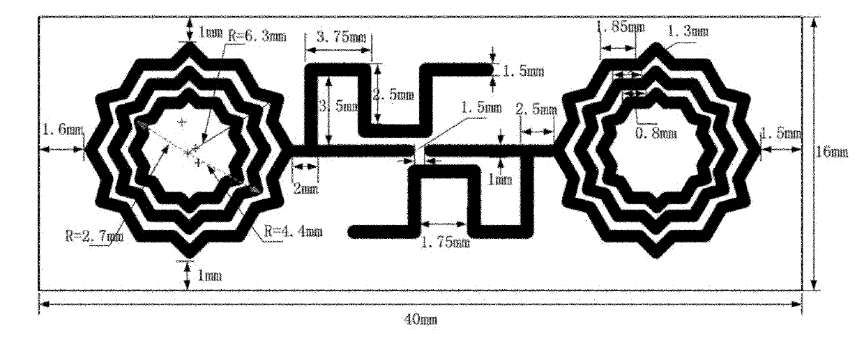
[0034] The present invention will be further described below in conjunction with embodiment and accompanying drawing.

[0035] see figure 1 , the embodiment of the present invention is provided with double-sided copper-clad epoxy resin substrate 1, both sides of the substrate 1 are covered with metal layers, and both layers use a symmetrical Koch fractal ring with a mirror image structure and a bent structure as a dipole The two arms of the child, the structure and size of one side are as follows figure 1 shown. The dimensions of the substrate 1 are: length 40mm±0.25mm, width 16mm±0.25mm, thickness 1.5mm±0.25mm. A disconnection gap A is provided on the symmetrical center line of the two arms of the dipole structure of the layer antenna, and antenna feeding points are provided on both sides of the disconnection gap A. The two-layer antenna structure is formed in a similar array form.

[0036] Substrate 1 is an FR4 substrate.

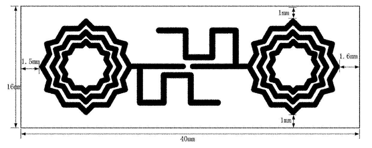
[0037] see figure 2The antenna structure of ...


PUM


Abstract

The invention provides a three-frequency Koch fractal ring mirror image dipole antenna, relates to a dipole antenna and provides a three-frequency Koch fractal ring mirror image dipole antenna with small size, large bandwidth, relatively low return loss, omnidirectional radiation characteristic, an mirror image structure, symmetrical Koch fractal rings and a bent structure. Three frequencies cover the common frequency bands ranging from 745 to 1,067 MHz and from 2,215 to 2,647 MHz of a radio frequency identification device (RFID) and the frequency band ranging from 1,617 to 1,912 MHz of mobile communication. A substrate is arranged; both sides of the substrate are coated with metal layers in which symmetrical Koch fractal rings and the bent structure which are provided with mirror image structures are taken as two dipole arms; the dipole arms are taken as radiation patches of the three-frequency Koch fractal ring mirror image dipole antenna; and two layers of antenna structures form asimilar array.

Description

technical field [0001] The invention relates to a dipole antenna, in particular to a three-frequency Koch fractal ring image dipole antenna with a mirror image structure, a symmetrical Koch fractal ring and a bending structure. Background technique [0002] Since RFID technology was developed by the U.S. Naval Research Laboratory (NRL) in 1937 to identify Allied aircraft, RFID technology has been widely used in logistics. The world's 100 largest Wal-Mart department store suppliers, including Oracle, SAP, and IBM, officially announced that by the end of 2005, all goods supplied to Wal-Mart department stores must have electronic product labels using RFID technology on the packaging, so that It has triggered a new upsurge in global research on the implementation of RFID technology for retail logistics management. [0003] In March 2007, the Global RF Lab Alliance (GRFLA) was established outside the EPC Global framework by nearly 20 research institutions from the United States,...

Claims


Application Information

Patent Timeline
Patent Type & Authority Patents(China)
IPC IPC(8): H01Q1/38H01Q5/01H01Q7/00H01Q5/10
Inventor 周建华罗勇游佰强胡秀丽王菁
Owner XIAMEN UNIV
Why Eureka
Try Eureka