
Method for identifying extra-high voltage direct current transmission line area inside and outside fault wavelet energy

An ultra-high voltage DC, wavelet energy technology, applied in fault locations, emergency protection circuit devices, electrical components, etc., can solve problems such as protection malfunction or refusal to operate, voltage conversion rate reduction, affecting the stable operation of DC systems, etc.

Active Publication Date: 2011-04-06
KUNMING UNIV OF SCI & TECH
View PDF4 Cites 36 Cited by
  • Summary
  • Abstract
  • Description
  • Claims
  • Application Information

AI Technical Summary

Problems solved by technology

[0002] The current high-voltage DC line protection used at home and abroad is mainly based on the traveling wave protection produced by ABB and SIEMENS. However, its protection is easily affected by the transition resistance, especially when an out-of-area fault occurs, after the fault traveling wave passes through the smoothing reactor and DC filter installed at the end of the DC line, the voltage conversion rate decreases. Small, easy to cause protection malfunction or refusal to operate, seriously affecting the stable operation of the DC system
Therefore, the main protection of the DC system based on the change rate criterion is easily affected by transition resistance, noise interference, fault distance, etc.

Method used


Image

  • Method for identifying extra-high voltage direct current transmission line area inside and outside fault wavelet energy
  • Method for identifying extra-high voltage direct current transmission line area inside and outside fault wavelet energy
  • Method for identifying extra-high voltage direct current transmission line area inside and outside fault wavelet energy

Examples


Embodiment Construction

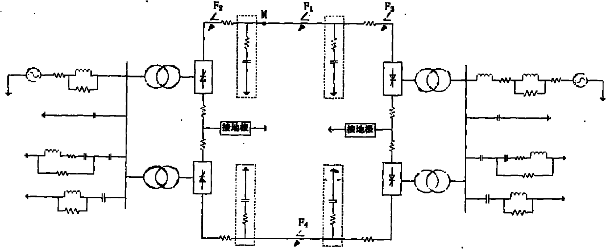
[0073] Simulation model such as figure 1 As shown, a positive ground fault occurred at a distance of 100km from the protection installation, the fault transition resistance was 0.1Ω, the time window length was 5ms, and the sampling frequency was 100kHz.

[0074] (1) After the DC line fails, the starting element starts immediately, and the two-pole DC voltage measured at the protection installation is u 1 (k), u 2 (k) Carry out the Karenbull pole-mode transformation on the two-pole line voltage to obtain the independent line-mode voltage u m1 (k).

[0075] u m1 (k)=u 1 (k)-u 2 (k) (7)

[0076] (2) Use db4 wavelet to compare the line mode voltage u m1 (k) Perform 4-layer wavelet decomposition to obtain low-frequency coefficients and high-frequency coefficients of wavelet decomposition at different scales.

[0077] (3) Find the wavelet energy sum of the high-frequency signal from the first scale to the fourth scale:

[0078] E 1 = X K = 1 N | d 1 ( k )...


PUM


Abstract

The invention relates to a method for identifying extra-high voltage direct current transmission line area inside and outside fault wavelet energy. The method comprises the following steps of: starting a starting element when a direct current fails and selecting bipolar direct current voltage data detected at a protection installation part after 5 ms of the fault, wherein the direct current voltage data are a discrete signal with sampling frequency of 100 kHz and sample sequence length of 500; finding out a direct current system line-mode voltage for four layers of wavelet decomposition by utilizing the bipolar direct current voltage so as to obtain low frequency coefficients and high frequency coefficients of the wavelet decomposition at different scales; and finding out wavelet high frequency energy from first scale to fourth scale and wavelet low frequency energy at the fourth scale according to the definition of wavelet energy of the signal at a certain scale, finding out the ratio of the wavelet high frequency energy to the wavelet low frequency energy, and comparing the size of the ratio of the wavelet high frequency energy to the wavelet low frequency energy so as to distinguish the inside faults and the outside faults. A large amount of simulation results show that the invention has good effect.

Description

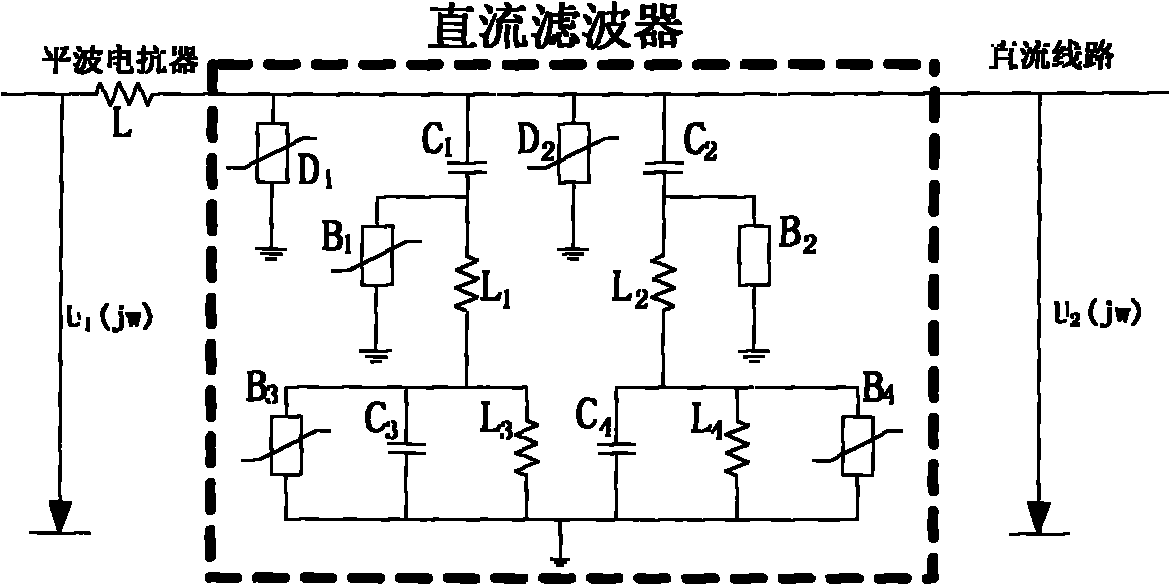
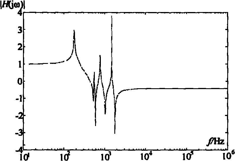
Technical field [0001] The invention relates to the technical field of power system relay protection, in particular to a method for identifying faults within and outside the UHV DC transmission line based on the line-mode voltage wavelet transform energy ratio. Background technique [0002] The current high-voltage DC line protection applied at home and abroad is mainly based on the traveling wave protection produced by ABB and SIEMENS. Its protection is based on the current change gradient, voltage traveling wave conversion rate and voltage behavior in the DC line when the DC transmission system fails. The amount of wave change is used as the criterion, but its protection is easily affected by the transition resistance, especially when an out-of-area fault occurs, after the fault traveling wave passes through the smoothing reactor and DC filter installed at the end of the DC line, its voltage conversion rate is reduced. If it is small, it is easy to cause protection malfunction ...

Claims


Application Information

Patent Timeline
IPC IPC(8): H02H7/26G01R31/08
Inventor 束洪春田鑫萃张广斌孙士云何廷一曹璞璘
Owner KUNMING UNIV OF SCI & TECH
Learn More