
Method for measurement of the three-dimensional density distribution in bones

a three-dimensional density and bone technology, applied in the field of three-dimensional density distribution measurement in bones, can solve the problem that the variation of bone density in a predetermined volume element cannot be exactly detected, and achieve the effect of optimal precision

Active Publication Date: 2007-02-06
SIEMENS HEALTHCARE GMBH
View PDF9 Cites 9 Cited by
  • Summary
  • Abstract
  • Description
  • Claims
  • Application Information

AI Technical Summary

Benefits of technology

[0009]An object of the invention is to provide an optimally precise method for measurement of the three-dimensional density distribution in bones.
[0011]With the inventive method, it is possible, in contrast to that prior art, to examine with spatial resolution a predetermined volume in a bone with regard to its density distribution. The measured volume can be determined precisely using the morphology of the bone in its position. As a consequence, it is possible to repeatedly measure the volume over a span of time of multiple years, and to make a conclusion about the course or the beginning of a bone disease from a comparison of the measured values. A significant advantage of the inventive method is that the density distribution in the irradiated (examined) volume can be quantitatively detected immediately with a single measurement, i.e. one rotation around the predetermined rotation angle.
[0013]It has proven to be advantageous, dependent on the respective rotation angle, to acquire at least 400 measurement values for each detector element per measurement pass. A “measurement pass”, means the acquisition of the measurement values during the rotation of the measurement arrangement. After the acquisition of the measurement values, the measurement arrangement is rotated back again into its initial position. A sufficiently precise conclusion about the density distribution in a bone can be made with the aforementioned number of measurement values. The method can be implemented relatively quickly. With a single measurement pass, a relatively large volume of 10 cm3 to 20 cm3 can be acquired. According to a further embodiment, the x-ray radiation is acquired by the detector elements with a spatial resolution of less than 0.4 mm, preferably with a spatial resolution in the range of 0.1 to 0.2 mm. The density distribution in a predetermined volume in the bone can be determined with an excellent precision.
[0015]The detector can be fashioned such that the entire volume to be irradiated can be acquired with a single rotation of the measurement arrangement. Furthermore, it has proven to be advantageous to use a detector with a bit depth of at least 12 bits. Conventional detectors can be used for this. It is advantageously not necessary to change the detector in terms of its design for measurement of the density distribution in the bones.
[0016]According to a further embodiment, two successive measurement passes can be implemented with different x-ray energies. It is thereby possible to acquire and to show bone portions with different densities in the volume. Reference is made to DE 696 20 869 T2, the content of which is incorporated herein by reference. The second measurement pass using a different x-ray energy can appropriately ensues after rotation of the measurement arrangement back into the initial position. This enables a particularly fast and effective method sequencing.
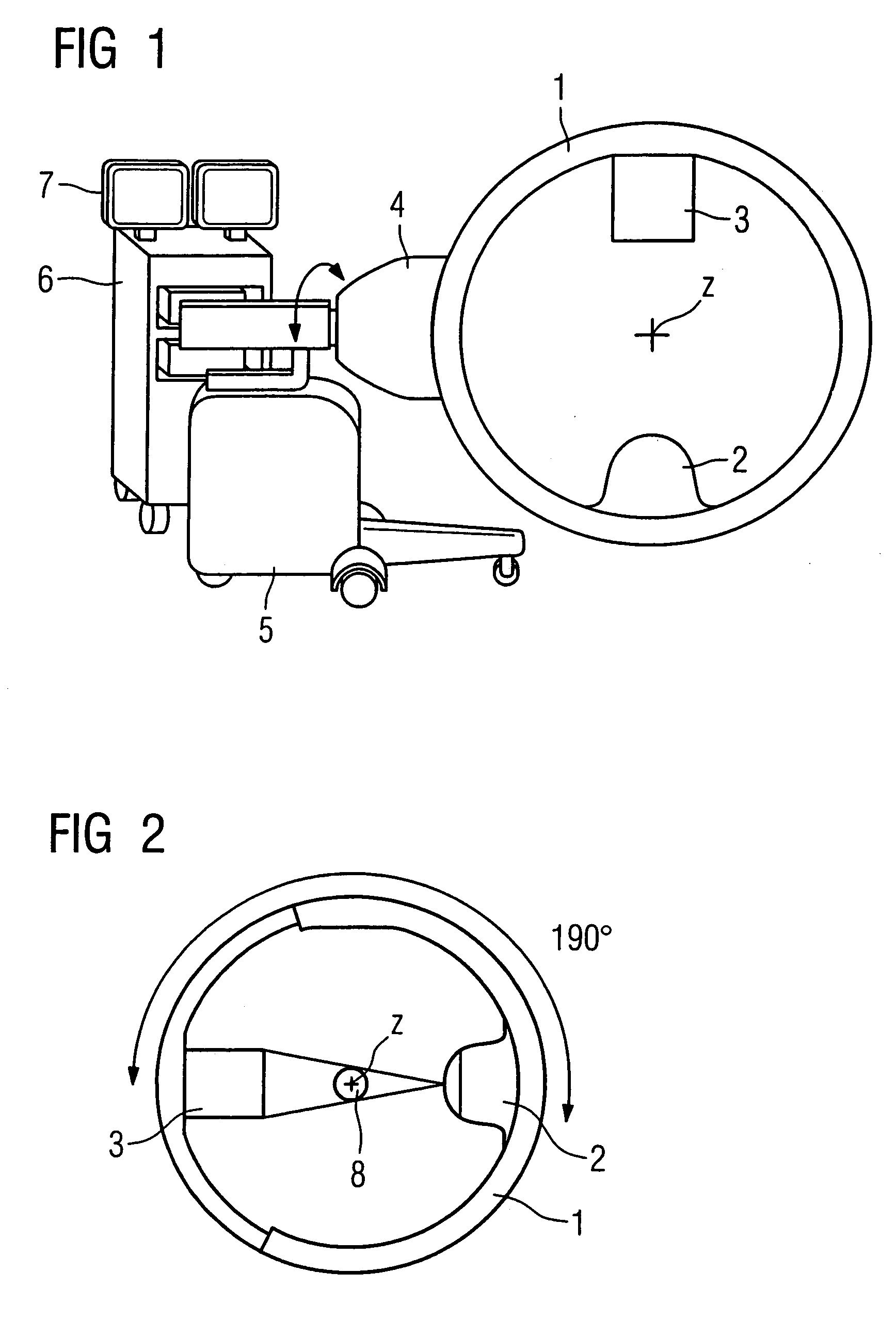
[0019]Furthermore, it has proven to be advantageous to mount the detector in the region of a first end of a carrier and to mount the x-ray source in the region of a second end of the carrier, fashioned in the form of a ring segment and rotatable around the rotation axis. A laminar detector in which the detector elements are arranged in an X / Y plane can be used as the detector. It is also possible to set the rotation plane of the measurement arrangement before the measurement by pivoting on a pivot axis. The inventive method thus can be implemented with a conventional apparatus, for example that of the company Siemens AG under the designation “SIREMOBIL Iso-C3D”. It is only necessary to install additional software effecting the function of the inventive method. The conventional x-ray apparatus is particularly universal. It is mobile and can be used in the operating room without the patient having to be repositioned. A simplified determination of the mineral content of bones is therewith possible, in particular for bed-ridden patients.

Problems solved by technology

Yet a variation of the bone density in a predetermined volume element still cannot be exactly detected.

Method used


Image

  • Method for measurement of the three-dimensional density distribution in bones
  • Method for measurement of the three-dimensional density distribution in bones

Examples


Embodiment Construction

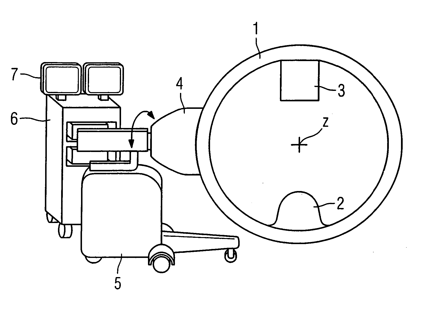
[0028]In FIG. 1, an x-ray source 2 and a detector 3 are mounted in opposing arrangement on a carrier 1 fashioned in the form of an annular segment. The detector 2, for example, can be a planar image detector that has a number of detector elements arranged in an X / Y plane. Naturally, instead of the planar image detector other detectors can also be used. Suitable detectors are known, for example, from R. F. Schulz: RöFo, volume 173, 2001, pages 1137 through 1146. The disclosure of this document is incorporated herein by reference.

[0029]The carrier 1 is held on a supporting element 4 such that it can rotate around a z-axis z perpendicular to the plane of the drawing. The supporting element 4 is—as is indicated with the double arrow—mounted on a cart 5 such that it can pivot around a y-axis (not shown here) perpendicular to the z-axis z. A high-voltage generator for generation of the high voltage necessary for the x-ray radiation can be provided in the cart 5. The cart 5 is connected wi...


PUM


Abstract

In a method for measurement of the three-dimensional density distribution in a bone, a two-dimensional or three-dimensional image reproducing the quantitative density distribution in the bone is generated using a measurement arrangement that can rotate around an angle of at most 300°.

Description

BACKGROUND OF THE INVENTION[0001]1. Field of the Invention[0002]The present invention concerns a method for measurement of the three-dimensional density distribution in bones as well as a C-arm x-ray apparatus for such a purpose.[0003]2. Description of the Prior Art[0004]An apparatus for measurement of the mineral content in bones is known from DE 696 20 869 T2 wherein the bones to be examined are successively irradiated with x-ray radiation of different energies. The mineral content in the bones is determined from the measured absorption of the x-ray radiation and using previously acquired reference values acquired by means of a reference subject. As a result, a two-dimensional density distribution is thereby obtained in g / cm2. Under the circumstances, an emerging (i.e., just beginning) variation of the bone density in the bones, in particular a decrease of the mineral content in a predetermined volume element cannot be detected with this known method. For diagnosis of osteoporosis...

Claims


Application Information

Patent Timeline
Patent Type & Authority Patents(United States)
IPC IPC(8): G01B15/02
CPCA61B6/505
Inventor FEHRE, JENSGRANZ, BERNDMERTELMEIER, THOMAS
Owner SIEMENS HEALTHCARE GMBH
Learn More