

Single-power supply cascade multi-level converter
A cascaded multilevel, single power supply technology, applied in the direction of converting AC power input to DC power output, electrical components, output power conversion devices, etc. The problem of back-to-back connection of AC, DC, and AC power converters cannot be realized due to the level of voltage, so as to achieve the effect of improving the utilization rate of DC voltage, easy expansion and low loss.
- Summary
- Abstract
- Description
- Claims
- Application Information
AI Technical Summary
Problems solved by technology
Method used
Image

Examples
Embodiment 1
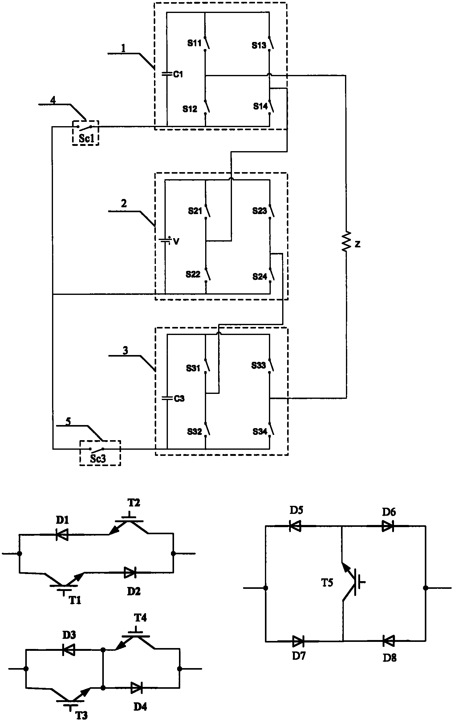
[0023] exist figure 1 In this topology, the topology includes inverter bridge (1), inverter bridge (2), inverter bridge (3), auxiliary switching tube (4) and auxiliary switching tube (5), where the inverter bridge (1) is: capacitor One end of (C1) is connected to the collector of the switching tube (S11) and the collector of the switching tube (S13), and the other end is connected to the emitter of the switching tube (S12) and the emitter of the switching tube (S14), and the switching tube (S11) The emitter of the switch is connected to the collector of the switch (S12), and the emitter of the switch (S13) is connected to the collector of the switch (S14); the inverter bridge (2) is: the positive pole of the DC voltage source is connected to the switch (S21) The collector and the collector of the switching tube (S23), the negative electrode is connected to the emitter of the switching tube (S22) and the emitter of the switching tube (S24), the emitter of the switching tube (S2...
Embodiment 2
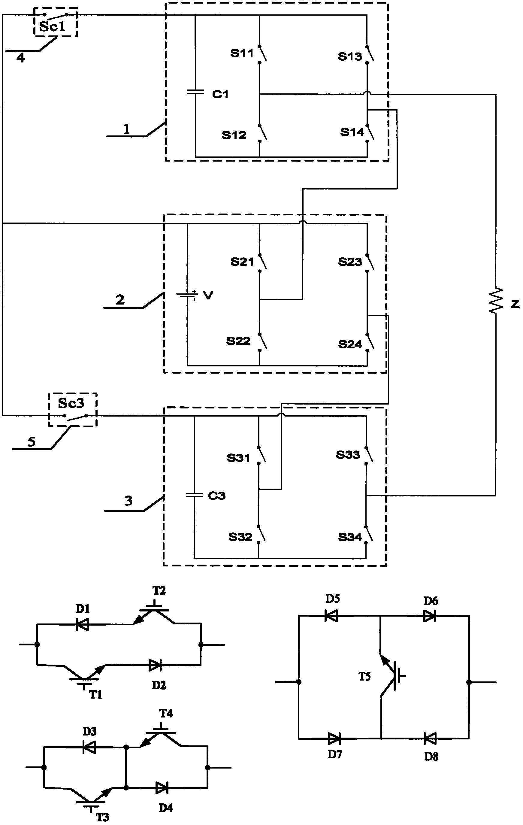
[0026] exist figure 2 Among them, the extension includes inverter bridge (1), inverter bridge (2), inverter bridge (3), auxiliary switching tube (4) and auxiliary switching tube (5), wherein the inverter bridge (1) is: capacitor One end of (C1) is connected to the collector of the switching tube (S11) and the collector of the switching tube (S13), and the other end is connected to the emitter of the switching tube (S12) and the emitter of the switching tube (S14), and the switching tube (S11) The emitter of the switch is connected to the collector of the switch (S12), and the emitter of the switch (S13) is connected to the collector of the switch (S14); the inverter bridge (2) is: the positive pole of the DC voltage source is connected to the switch (S21) The collector and the collector of the switching tube (S23), the negative electrode is connected to the emitter of the switching tube (S22) and the emitter of the switching tube (S24), the emitter of the switching tube (S21)...
Embodiment 3
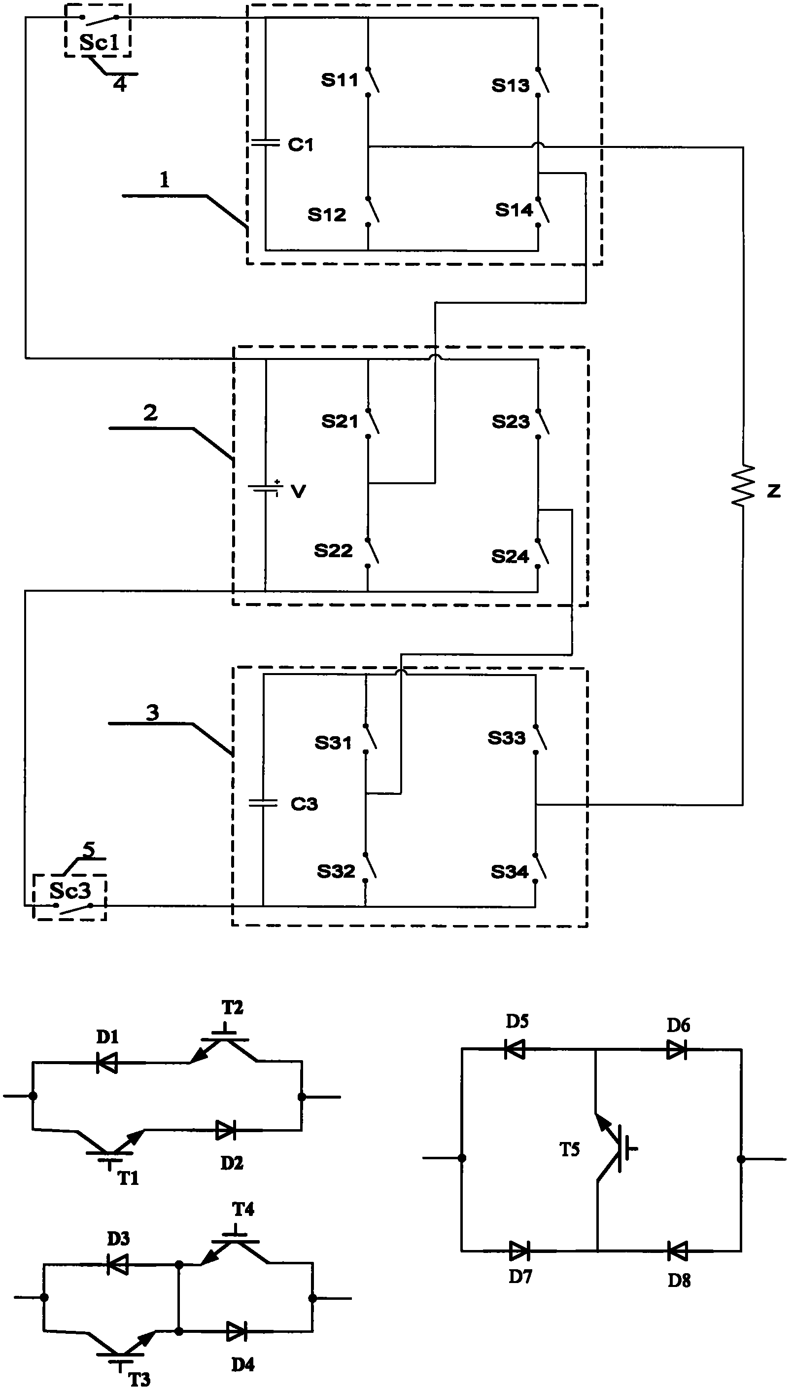
[0029] exist image 3 Among them, the extension includes inverter bridge (1), inverter bridge (2), inverter bridge (3), auxiliary switching tube (4) and auxiliary switching tube (5), wherein the inverter bridge (1) is: capacitor One end of (C1) is connected to the collector of the switching tube (S11) and the collector of the switching tube (S13), and the other end is connected to the emitter of the switching tube (S12) and the emitter of the switching tube (S14), and the switching tube (S11) The emitter of the switch is connected to the collector of the switch (S12), and the emitter of the switch (S13) is connected to the collector of the switch (S14); the inverter bridge (2) is: the positive pole of the DC voltage source is connected to the switch (S21) The collector and the collector of the switching tube (S23), the negative electrode is connected to the emitter of the switching tube (S22) and the emitter of the switching tube (S24), the emitter of the switching tube (S21) ...
PUM
 Abstract
Description
Claims
Application Information