Automobile auxiliary brake-powered speed-reduction friction device and braking method thereof

A friction device and automobile auxiliary technology, applied in hydraulic brake transmission, vehicle parts, transportation and packaging, etc., can solve the problems of low friction coefficient, increase of wheel and ground, limited contact area, etc., achieve simple process, reduce Braking distance and the effect of reducing traffic accidents

Inactive Publication Date: 2011-04-13
于宥源
View PDF6 Cites 24 Cited by
  • Summary
  • Abstract
  • Description
  • Claims
  • Application Information

AI Technical Summary

Problems solved by technology

[0003] During the braking process of a car, the braking energy is mainly consumed in the brakes, mechanical wear and friction between the wheels and the ground. The vehicle brakes currently used include friction brakes (disc and drum), retarders (hydraulic, electric and pneumatic) , engine braking and anti-lock braking system (ABS), etc., and domestic and foreign scientific research institutions and automobile manufacturers are also mainly engaged in related work on the brakes. It also mainly focuses on increasing the friction coefficient between the wheel and the ground. However, since the contact area between the tire and the ground is limited, and the friction between the wheel and the ground is rolling friction, the friction coefficient is low. Therefore, increasing the friction between the wheel and the ground is limited

Method used


Image

  • Automobile auxiliary brake-powered speed-reduction friction device and braking method thereof
  • Automobile auxiliary brake-powered speed-reduction friction device and braking method thereof
  • Automobile auxiliary brake-powered speed-reduction friction device and braking method thereof

Examples


Embodiment 1

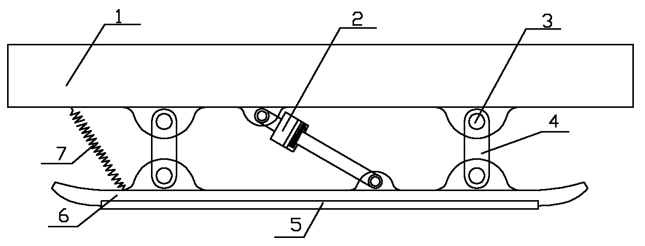
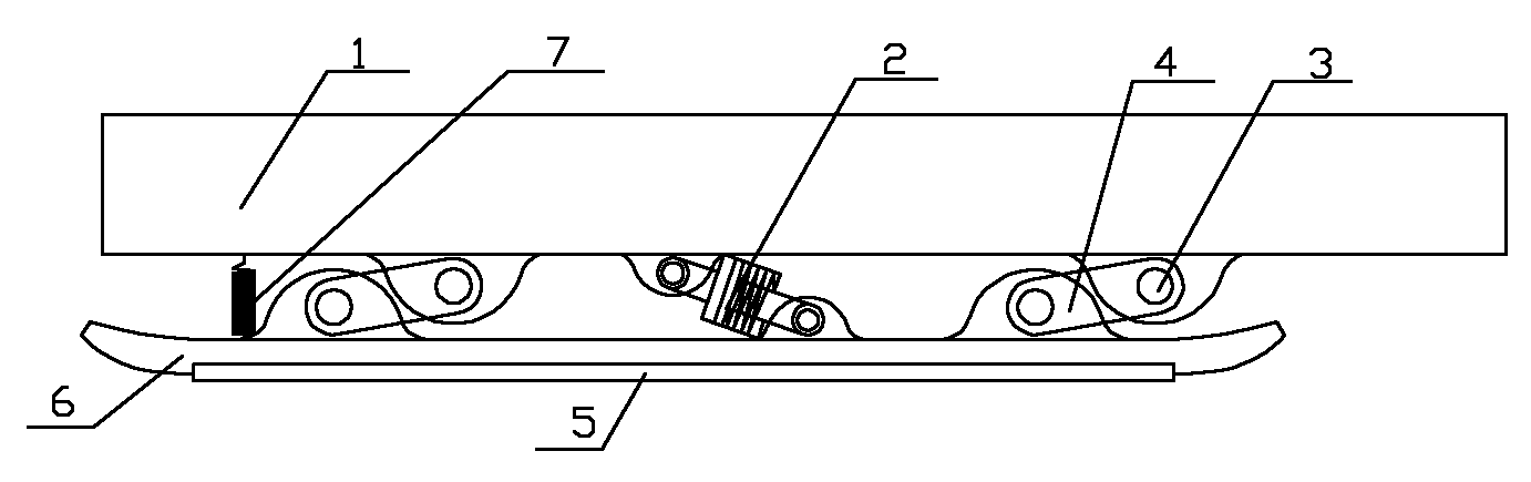
[0043] see figure 1 , figure 2 , figure 1 , figure 2 It is a connection form in which the automobile chassis longitudinal beam 1 is connected to the friction brake pedal 6 in the present invention. The automobile chassis longitudinal beam 1 and the friction brake pedal 6 are directly connected through two connecting rods 4, hydraulic cylinder 2 and spring 7, and the connecting rod 4 are respectively connected with automobile chassis longitudinal beam 1 and friction brake pedal 6 by pin 3, and friction plate 5 is arranged on the following riveting or screw connection of friction brake pedal 6, when the present invention stops working, then just as figure 2 shown.

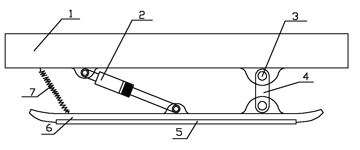
[0044] see image 3 , Figure 4 , image 3 , Figure 4 It is another connection form that the automobile chassis longitudinal beam 1 is connected with the friction brake pedal 6 in the present invention. The automobile chassis longitudinal beam 1 is directly connected with the friction brake pedal 6 through...


PUM


Abstract

The invention relates to an automobile brake device and a braking method thereof, in particular to an automobile auxiliary brake-powered speed-reduction friction device and a braking method thereof. The automobile auxiliary brake-powered friction device comprises an automobile chassis longitudinal beam, wherein the lower part of the automobile chassis longitudinal beam is provided with a friction brake pedal; a friction plate is arranged below the friction brake pedal; and a transmission mechanism which is connected with a control circuit is also arranged between the automobile chassis longitudinal beam and the friction brake pedal. The device and the method can increase a braking force effectively by using the friction force generated by friction between the friction brake pedal and the ground when an automobile is braked in emergency or runs down a slope continuously, so that the braking distance in emergent brake is reduced or traffic safe accidents caused by the braking failure of a drum brake at an overhigh temperature when the automobile runs down the slope continuously.

Description

1. Technical field [0001] The invention relates to an automobile brake device and a brake method thereof, in particular to an automobile auxiliary brake booster deceleration friction device and a brake method thereof. 2. Background technology [0002] Braking device: It is the assembly of all the braking systems installed on the vehicle, and its function is to slow down or stop the vehicle in motion or keep the vehicle in motion. [0003] During the braking process of a car, the braking energy is mainly consumed in the brakes, mechanical wear and friction between the wheels and the ground. The vehicle brakes currently used include friction brakes (disc and drum), retarders (hydraulic, electric and pneumatic) , engine braking and anti-lock braking system (ABS), etc., and domestic and foreign scientific research institutions and automobile manufacturers are also mainly engaged in related work on the brakes. It also mainly focuses on increasing the friction coefficient between...

Claims


Application Information

Patent Timeline
Patent Type & Authority Applications(China)
IPC IPC(8): B60T1/14B60T11/10
CPCB60T1/14
Inventor 于宥源杨建辉于佳菲于晓芳
Owner 于宥源
Why Eureka
Try Eureka