Blade for bituminous pavement milling machine and grooving machine

A technology for asphalt pavement and milling machine, which is applied to roads, roads, road repair and other directions, can solve the problems of wasting manpower, large resistance, and shortening the service life of the engine, and achieves the effect of high operation efficiency, reasonable design, and reduced resistance.

Active Publication Date: 2011-04-13
HENAN LUDA HIGHWAY TRANSPORTATION TECH CO LTD
View PDF6 Cites 8 Cited by
  • Summary
  • Abstract
  • Description
  • Claims
  • Application Information

AI Technical Summary

Problems solved by technology

[0004] The milling and slotting blades used in the above-mentioned small milling machine and small slotting machine are the same. The main structure of the blade is that the front end of the cutter body is welded and connected with a straight cutter head. The main disadvantage of this blade is that the straight cutter head is The blade is not sharp, there is only one tip, the tip is easily damaged durin...

Method used


Image

  • Blade for bituminous pavement milling machine and grooving machine
  • Blade for bituminous pavement milling machine and grooving machine
  • Blade for bituminous pavement milling machine and grooving machine

Examples


Embodiment 1

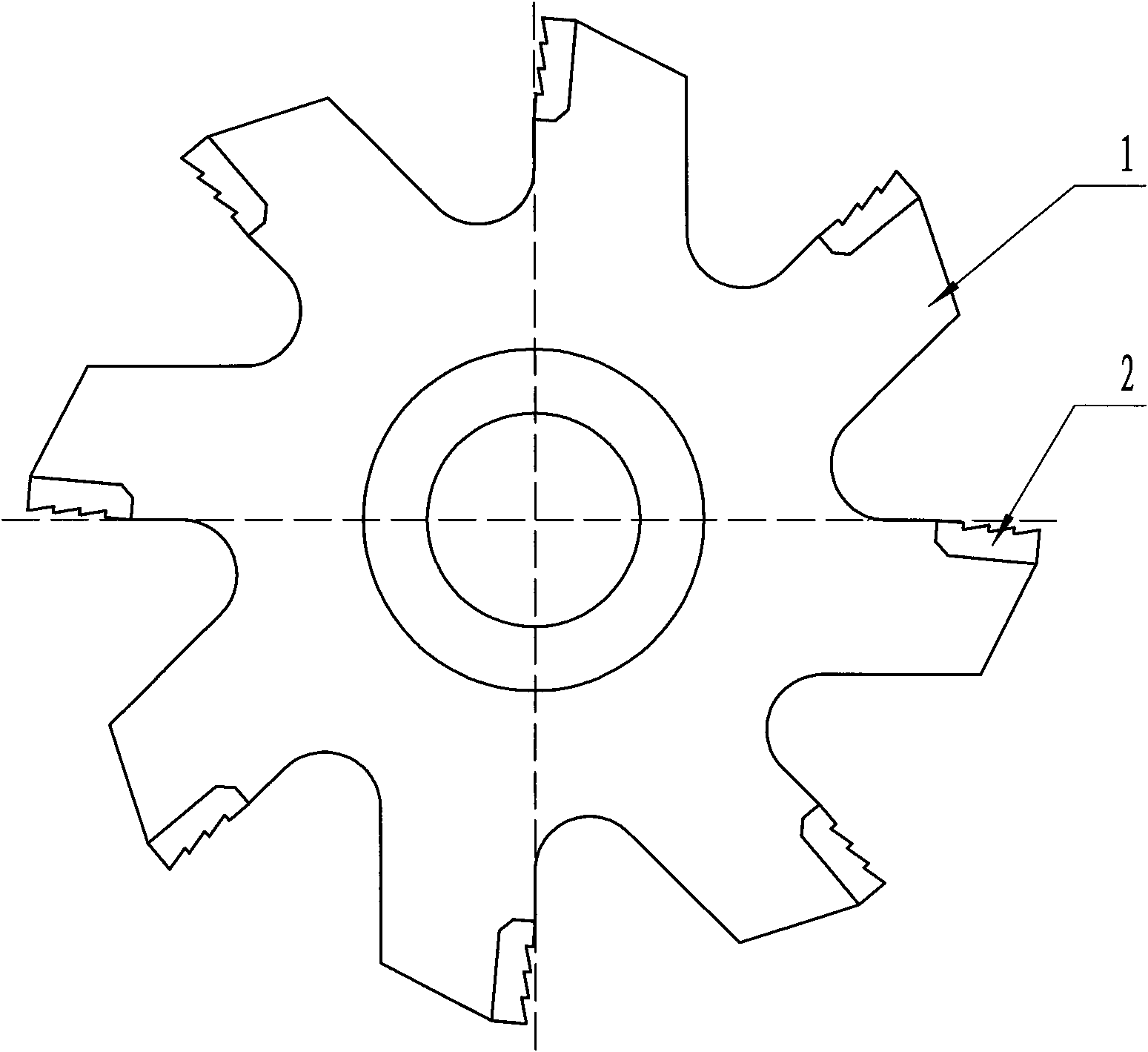
[0016] exist figure 1 , 2 Among them, the blades of the asphalt road milling machine and slotting machine in this embodiment are composed of a cutter body 1 and a cutter head 2 .

[0017] The cutter body 1 of this embodiment has a disc-shaped structure, which is the same as the existing cutter body 1. Eight cutter heads 2 are welded and connected to the front end of the cutter body 1, and the cutter heads 2 are alloy steel materials.

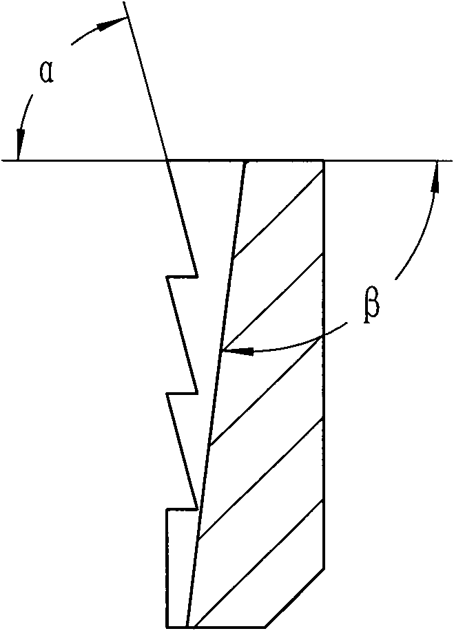
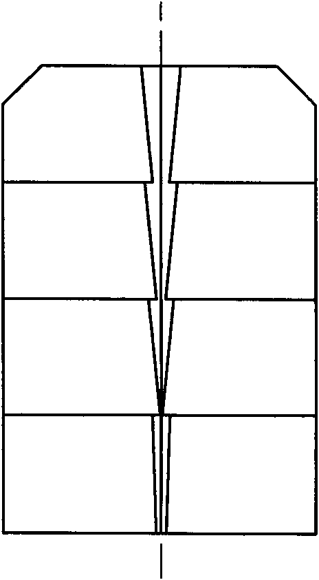
[0018] figure 2 , 3 , 4 shows the structure diagram of the cutter head 2 of this embodiment. exist figure 2 , 3 In 4, the front cutting surface of the cutter head 2 is processed into a zigzag cutting edge arranged in a radial direction and connected as a whole, wherein one tooth at the root is a straight-toothed cutting edge, and the remaining teeth are helical-toothed cutting edges. In this embodiment The front end face of the cutter head 2 is processed with three helical-toothed cutting blades. The specific number of helical-toothed cu...

Embodiment 2

[0020] In this embodiment, the front cutting surface of the cutter head 2 is processed into a zigzag cutting edge arranged in a radial direction, one tooth at the root is a straight-toothed cutting edge, and the remaining three teeth are helical-toothed cutting edges , the cutting angle α of the straight-toothed cutting edge is 90°, and the cutting angle α of the helical-toothed cutting edge is 70°. The center line of the front cutting surface of the cutter head 2 is processed with a middle split edge groove, the middle split edge groove is a V-shaped groove, the angle γ between the two sides of the middle split edge groove is 28°, and the clip between the bottom of the groove and the outer end surface of the cutter head 2 The angle β is 93°. Other components and the coupling relationship of the components are the same as in Embodiment 1.

Embodiment 3

[0022] In this embodiment, the front cutting surface of the cutter head 2 is processed into a zigzag cutting edge arranged in a radial direction, one tooth at the root is a straight-toothed cutting edge, and the remaining three teeth are helical-toothed cutting edges , the cutting angle α of the straight-toothed cutting edge is 90°, and the cutting angle α of the helical-toothed cutting edge is 80°. The center line of the front cutting surface of the cutter head 2 is processed with a middle split edge groove, the middle split edge groove is a V-shaped groove, the angle γ between the two sides of the middle split edge groove is 28°, and the clip between the bottom of the groove and the outer end surface of the cutter head 2 The angle β is 97°. Other components and the coupling relationship of the components are the same as in Embodiment 1.


PUM


Abstract

The invention provides a blade for a bituminous pavement milling machine and a grooving machine. A tool bit is arranged at the front end of a cutter body; 45-degree chamfers are manufactured at the rear end of the root of the tool bit and on both sides of the front end face of the tool bit; the tool bit is that: an integrally connected sawtooth-shaped cutting edge is arranged in the radial direction of the front cutting face of the tool bit; and a cutting edge division groove is formed on the central line of the front cutting face of the tool bit. By using the blade, the cutting edge of the tool bit is very sharp, so the area of the cutting edge is increased and a cutting resistance is reduced; in the process of milling or grooving, even the tip of the first helical-form cutting edge at the head is damaged, the other helical-form cutting edges and straight-tooth cutting edges still have strong cutting forces; and the middle cutting edge division groove allows the cut-down bituminous concrete to be easily drained. The blade for the bituminous pavement milling machine and the grooving machine has a rational design and high working efficiency, can be used for milling and grooving, and can be used on the milling machine.

Description

technical field [0001] The invention belongs to the technical field of pavement maintenance devices and equipment or devices for processing completed pavements, and in particular relates to pavement maintenance devices for building, repairing, repairing or demolishing roads or auxiliary equipment similar to pavements. Background technique [0002] my country's asphalt roads are growing rapidly, and a highway network has been formed across the country. Due to the rapid increase in traffic volume and severe overloading, after a period of use, the asphalt road surface will be damaged to varying degrees, and some or all of it needs to be repaired. The main diseases of asphalt roads are ruts, potholes, pockets, and network cracks. The ruts, potholes, and pockets on the asphalt pavement affect the driving speed, driving safety and driving comfort. Cracks appear on the asphalt pavement. After maintenance treatment, rainwater infiltrates continuously, the asphalt road foundation wil...

Claims


Application Information

Patent Timeline
IPC IPC(8): E01C23/085E01C23/088E01C23/09
Inventor 聂联法
Owner HENAN LUDA HIGHWAY TRANSPORTATION TECH CO LTD
Why Eureka
Try Eureka