Method and device for bringing a manipulator to a standstill

A technology of manipulators and computing devices, applied in engineering safety devices, instruments, simulators, etc., can solve the problem of high monitoring costs

Inactive Publication Date: 2011-04-13
库卡实验仪器有限公司
View PDF5 Cites 15 Cited by
  • Summary
  • Abstract
  • Description
  • Claims
  • Application Information

AI Technical Summary

Problems solved by technology

However, the associated perso

Method used


Image

  • Method and device for bringing a manipulator to a standstill
  • Method and device for bringing a manipulator to a standstill
  • Method and device for bringing a manipulator to a standstill

Examples


Embodiment Construction

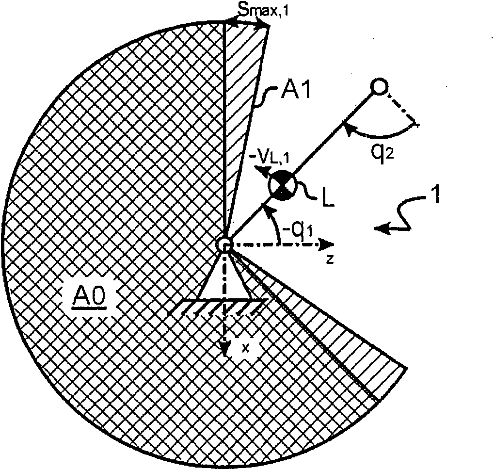
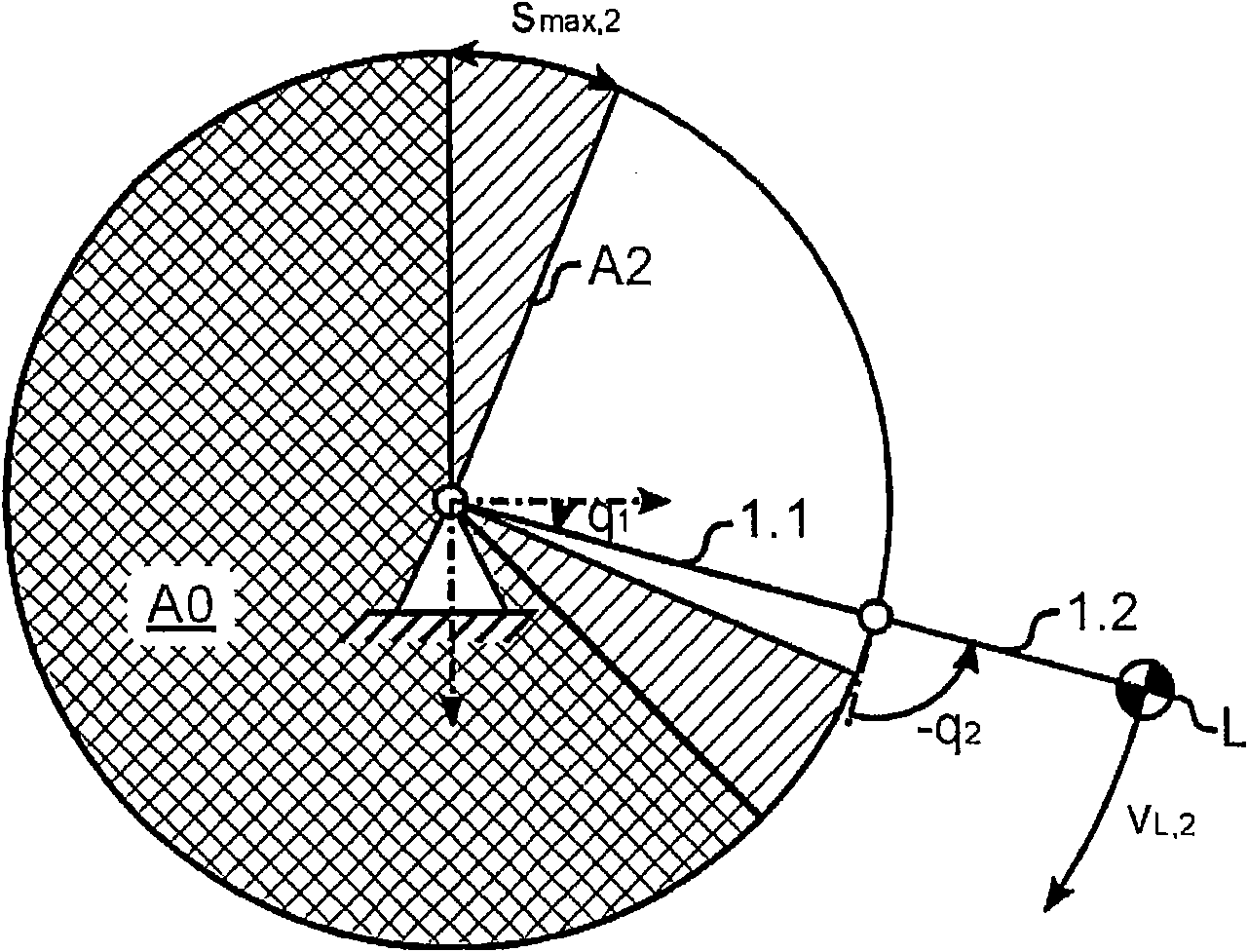
[0038] For better overview, the invention is described below with reference to simplified examples. for this in figure 1 and figure 2 is shown with two limbs 1.1, 1.2 (see figure 2 ) of a two-axis bent-arm robot 1, the two limbs 1.1, 1.2 are connected to each other by a revolving joint, and the joint angle q of the revolving joint 1 or q 2 Can be adjusted by the driving device to move the load L, the inertia parameters of the load L, especially the mass m, the center of gravity position r TCP.L and the moment of inertia or inertia tensor J relative to the tool center point TCP L is known.

[0039] exist figure 1 In , robot 1 utilizes the folded arm 1.2(q 2 =90°) to make the load L move at a Cartesian velocity V on a circular trajectory L,1 Move upwards (v figure 2 Using the open arm 1.2 and with a large angular velocity dq 1 / dt Movement down.

[0040] In order to protect operators and equipment and avoid self-collision, it is set in the foundation of robot 1 and i...


PUM


Abstract

A method according to the invention for stopping a manipulator (1) includes these steps: advance simulation of stopping distances for different states (q, dq/dt, L) and/or braking force profiles ([tau]) of the manipulator (S10), estimating of an upper limit as the stopping distance (smax) on the basis of the stopping distances simulated in advance (S120), monitoring a zone (A0; A1; A2), and decelerating the manipulator (1) when a zone is violated, wherein the monitored zone is defined variably (S130) during operation on the basis of the stopping distance (smax) of the manipulator.

Description

technical field [0001] The invention relates to a method and a device for stopping a manipulator, in particular a robot, and for determining a braking distance of the manipulator. Background technique [0002] In particular in the field of robot applications where safety is of paramount importance, it is known that a protective field should be specified, for example in a world coordinate system, into which a limb of the robot or a reference point such as a TCP must not enter. If a violation of the zone is identified, the robot is brought to a safe stop. [0003] Here, however, the robot continues to enter the protected area due to its inertia, downtime (Totzeiten) and the lag between the invasion area and the monitoring reaction. [0004] Patent document DE 102008013431 A1 proposes that in order to stop the machine before the danger occurs, the maximum available delay time is determined based on the monitored distance between the human and the machine's working area and the...

Claims


Application Information

Patent Timeline
IPC IPC(8): F16P3/14B25J9/18G05B19/4061
CPCG05B2219/39098B25J9/1674G05B2219/39082B25J19/0004
Inventor 安德烈亚斯·奥恩哈默玛尔库斯·爱森金尔安德烈亚斯·哈格瑙尔曼弗雷德·许滕霍夫尔
Owner 库卡实验仪器有限公司
Why Eureka
Try Eureka