Composite phase-transition heat exchanging device for warming clean gas fume and recovering exhaust heat after wet desulphurization

A composite phase inversion heat and wet desulfurization technology, which is applied in the field of composite phase inversion heat devices, can solve the problems of no real success, waste of water resources, large steam consumption, etc., so as to reduce the amount of cooling water and improve thermal efficiency. , the effect of saving water resources

Inactive Publication Date: 2011-04-13
山西中源科扬节能服务有限公司
View PDF8 Cites 32 Cited by
  • Summary
  • Abstract
  • Description
  • Claims
  • Application Information

AI Technical Summary

Problems solved by technology

This technical scheme once obtained people's general attention, but does not really obtain success so far
The reason is that there are obvious deficiencies: first, the heat exchanger consumes a large amount of steam, and the heat loss accounts for about 2% of the boiler efficiency, and the economy is poor; second, this method does not consider how to absorb and utilize the original flue gas before entering the desulfurization tower. Low-temperature waste heat, in order to improve the thermal efficiency of the boiler as much as possible, but also because a large amount of cooling water needs to be consumed to achieve the process requirements of reducing the temperature of the original flue gas entering the d...

Method used


Image

  • Composite phase-transition heat exchanging device for warming clean gas fume and recovering exhaust heat after wet desulphurization
  • Composite phase-transition heat exchanging device for warming clean gas fume and recovering exhaust heat after wet desulphurization
  • Composite phase-transition heat exchanging device for warming clean gas fume and recovering exhaust heat after wet desulphurization

Examples


Embodiment

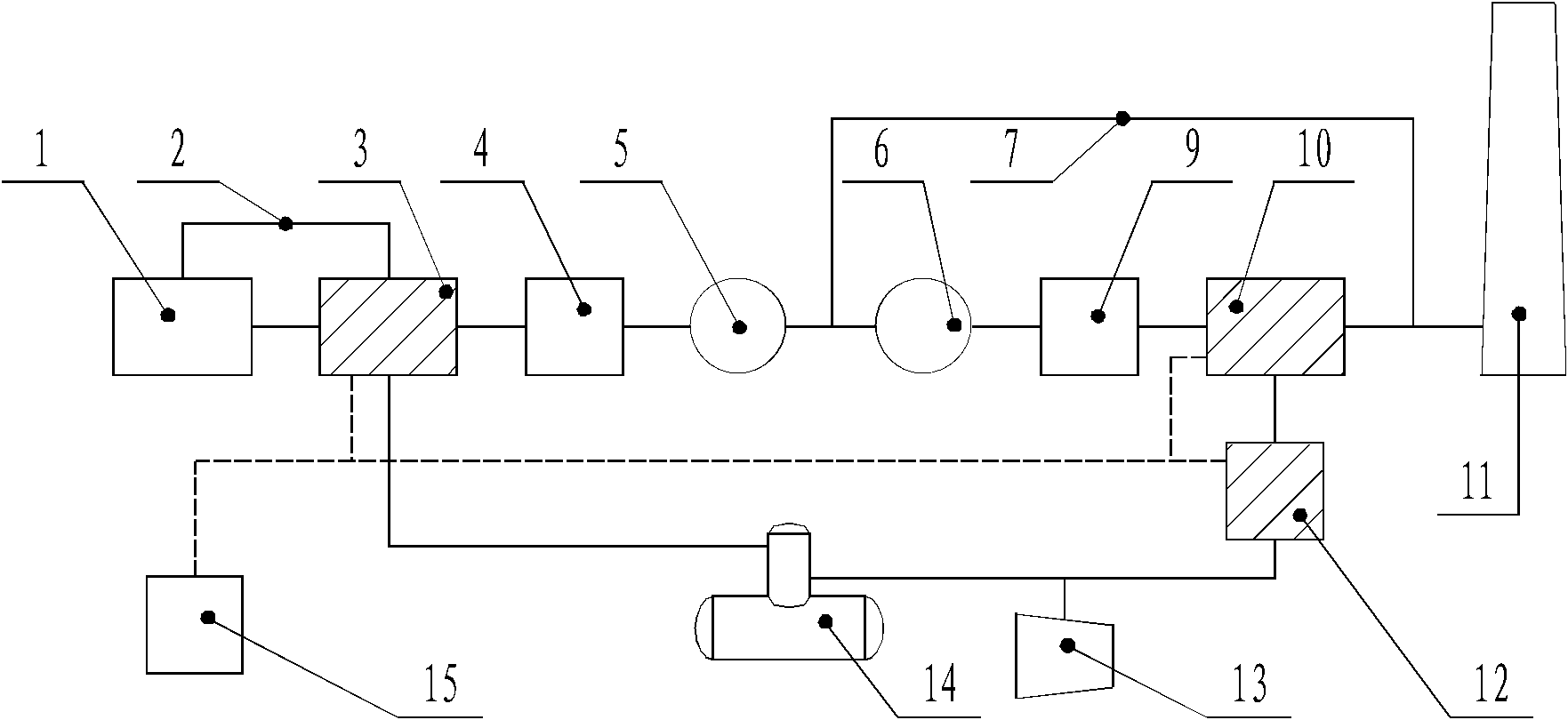
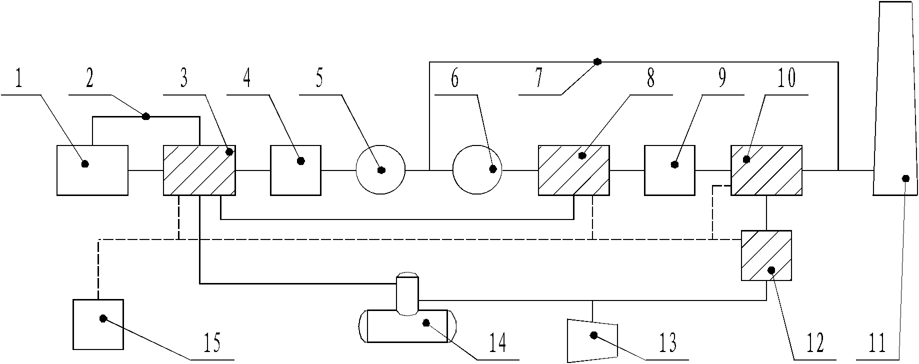
[0035] This embodiment includes: I-level phase-change heat exchanger 3, electric control cabinet 15, III-level phase-change heat exchanger 10, and I-level phase-change heat exchanger 3 are connected to III-level phase-change heat exchanger 10 successively through pipelines, constant temperature The humidifier 12 and the first-stage phase-change heat exchanger 3 are connected to the electric control cabinet 15 through wiring, and the constant-temperature humidifier 12 is connected to the first-stage phase-change heat exchanger 3 through pipelines.

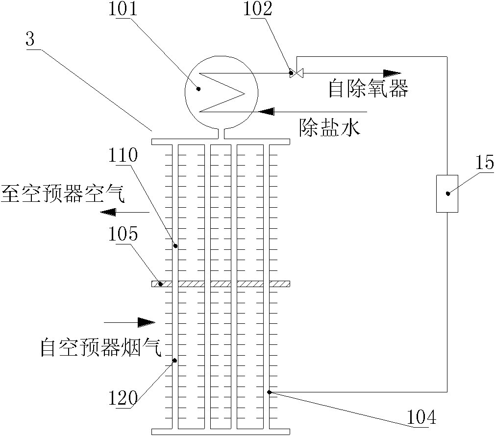
[0036] The first-stage phase-change heat exchanger 3 described in this embodiment includes: a steam drum 101, a desalinated water regulating valve 102, a temperature measuring instrument 104, and a phase change lower section 120, which is arranged after the air preheater 1 of the boiler system In the flue of the flue, the phase change lower section 120 of the I-stage phase-change heat exchanger 3 is sequentially connected in series t...


PUM


Abstract

The invention relates to a composite phase-transition heat exchanging device for warming clean gas fume and recovering exhaust heat after wet desulphurization in the technical field of heat transmission. The device comprises a level-I phase-transition heat exchanger, a constant temperature humidifier, a level-III phase-transition heat exchanger and an electrical cabinet, wherein the level-I phase-transition heat exchanger is connected with the level-III phase-transition heat exchanger and the constant temperature humidifier in turn through pipelines; the level-I phase-transition heat exchanger is connected with the electrical cabinet through connecting wires; and the constant temperature humidifier is in return connection with the level-I phase-transition heat exchanger through pipelines. Aiming at the defects of the prior art, multiple technical advantages hidden in phase-transition heat exchanging are fully developed, the clean gas fume temperature is improved after the wet desulphurization by using low temperature exhaust heat carried by the gas fume in a boiler system according to different thermotechnical states presented by the original gas fume and relevant physicochemical characteristics as well as relevant physical characteristics and energy required by warming of the clean gas fume in a boiler equipment system, national gas fume emission standards are met and the thermal efficiencies of boilers are improved.

Description

technical field [0001] The invention relates to a device in the technical field of heat transfer, in particular to a composite phase-change heat device for raising the net flue gas after wet desulfurization and recovering waste heat. Background technique [0002] The use of limestone wet flue gas desulfurization is a desulfurization method commonly used in large power plants. However, the use of wet lime / limestone desulfurization process (FCD) generally has severe low-temperature corrosion of the flue gas heat exchange system, which cannot heat the clean flue gas to the required temperature, and often makes the heat exchange equipment completely ineffective, eventually causing extremely serious The problem of secondary pollution. In other words, using a flue gas heater to increase the net flue gas temperature has long been a technical problem that has not been well resolved in the world. For example, according to the "Technical Handbook of Wet Flue Gas Desulfurization in T...

Claims


Application Information

Patent Timeline
IPC IPC(8): F23J15/00
CPCY02E20/34
Inventor 杨本洛
Owner 山西中源科扬节能服务有限公司
Why Eureka
Try Eureka