

Measuring device and method of apparent viscosity of saturated sand in high pore pressure ratio state
A technology of high porosity and apparent viscosity of sandy soil, applied in the direction of measuring devices, flow characteristics, instruments, etc., can solve the problems of high apparent viscosity, inability to flow smoothly, and high velocity of fluid movement, so as to improve the test efficiency and avoid The effect of pipeline damage and uniform water output
- Summary
- Abstract
- Description
- Claims
- Application Information
AI Technical Summary
Problems solved by technology
Method used
Image

Examples
Embodiment Construction
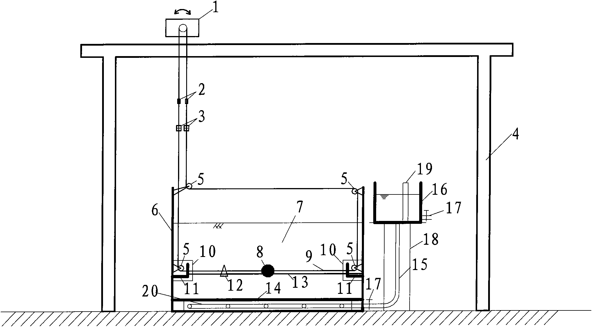
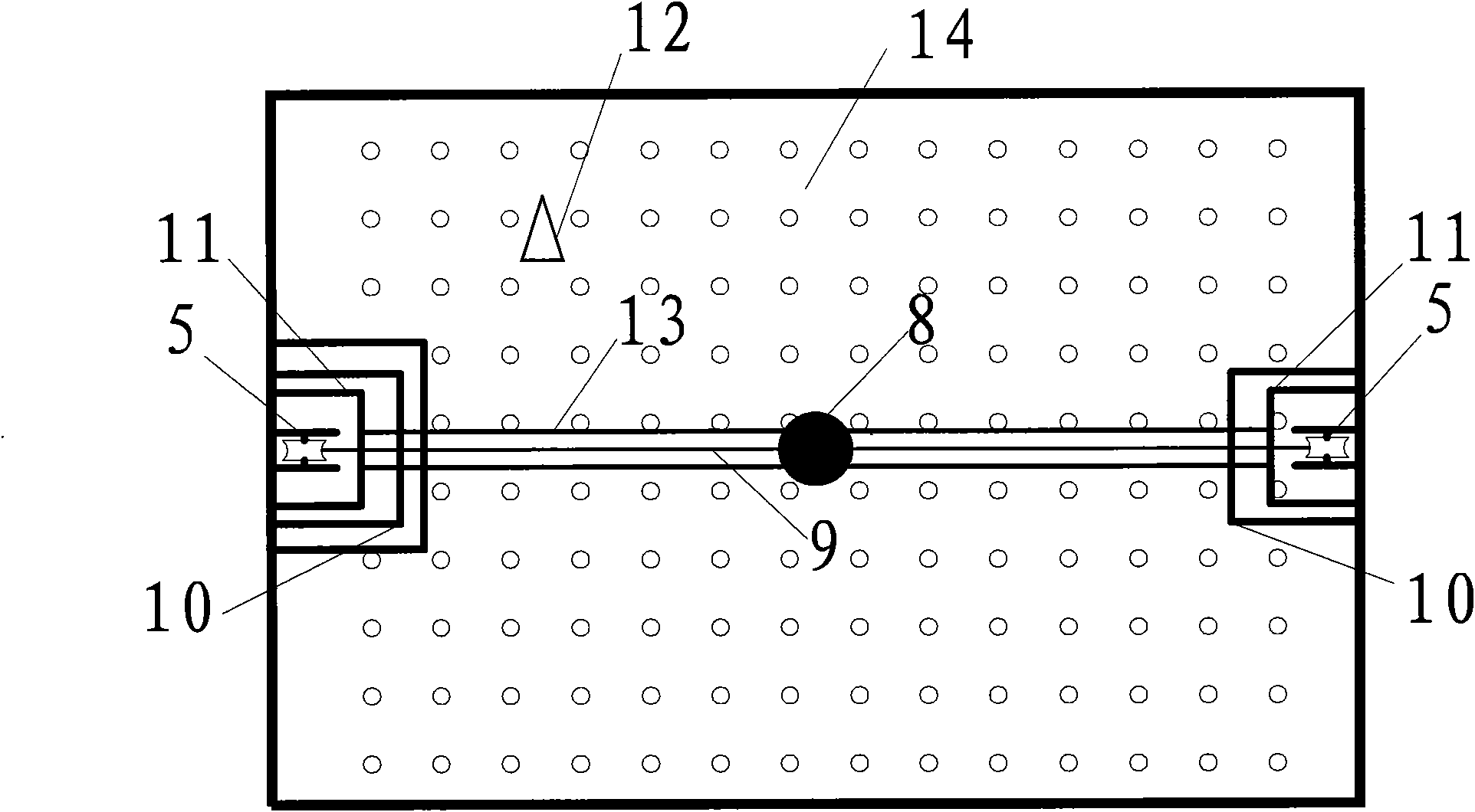
[0053] A device for measuring the apparent viscosity of saturated sandy soil with a high pore pressure ratio, comprising an external water tank (16), a hose (15) and a fixed model box (6), as well as a low-speed adjustable motor (1), a dynamic Tension sensor (2), dynamic displacement sensor (3), fixed pulley (5), rigid ball (8), traction rope (9), fixed pulley block protection box (10), track bracket (11), dynamic hole pressure sensor ( 12), track (13), hard board (14), water control valve (17), water tank support (18), scale (19), outlet pipe (20), hard board support (21).
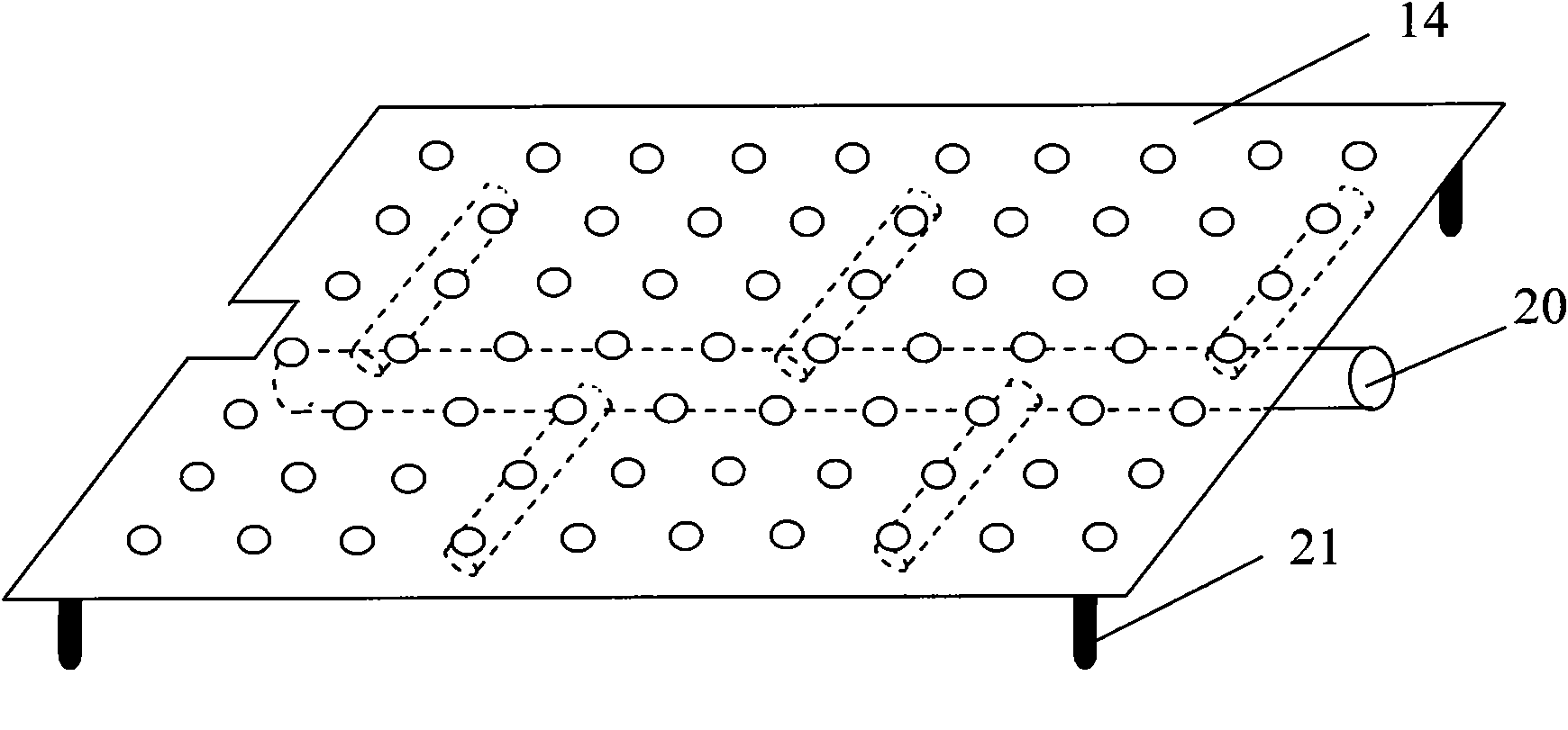
[0054] The hard plate (14) of model box (6) bottom, has uniform circular hole, and circular hole diameter 5mm, and hole pitch is 20mm, and hard plate (14) size is slightly smaller than size in model box (6). The hard plate (14) is 8mm away from the bottom of the model box (6), and the support (21) is welded at the four corners of the bottom, so that it is placed on the bottom of the model box (6). Hard p...
PUM
| Property | Measurement | Unit |
|---|---|---|
| Hole diameter | aaaaa | aaaaa |
| Hole spacing | aaaaa | aaaaa |
Abstract
Description
Claims
Application Information