Micro capacitance measurement method and special device

A measurement method and micro-capacitance technology, applied in the direction of measuring devices, measuring electrical variables, measuring resistance/reactance/impedance, etc., can solve the problems of large charging and discharging current of the measured capacitor, unstable voltage source, and large charging and discharging current. Achieve the effect of good stability, easy guarantee of precision and elimination of stray capacitance

A measurement method and micro-capacitance technology, applied in the direction of measuring devices, measuring electrical variables, measuring resistance/reactance/impedance, etc., can solve the problems of large charging and discharging current of the measured capacitor, unstable voltage source, and large charging and discharging current. Achieve the effect of good stability, easy guarantee of precision and elimination of stray capacitance

CN102012464AInactive Publication Date: 2011-04-13彭建学 +1

Image

  • Micro capacitance measurement method and special device
  • Micro capacitance measurement method and special device
  • Micro capacitance measurement method and special device

Examples


Embodiment Construction

[0026] In order to make the technical means, innovative features, objectives and effects achieved by the present invention easy to understand, the present invention will be further described below in conjunction with specific illustrations.

[0027] Principle of the present invention is as follows:

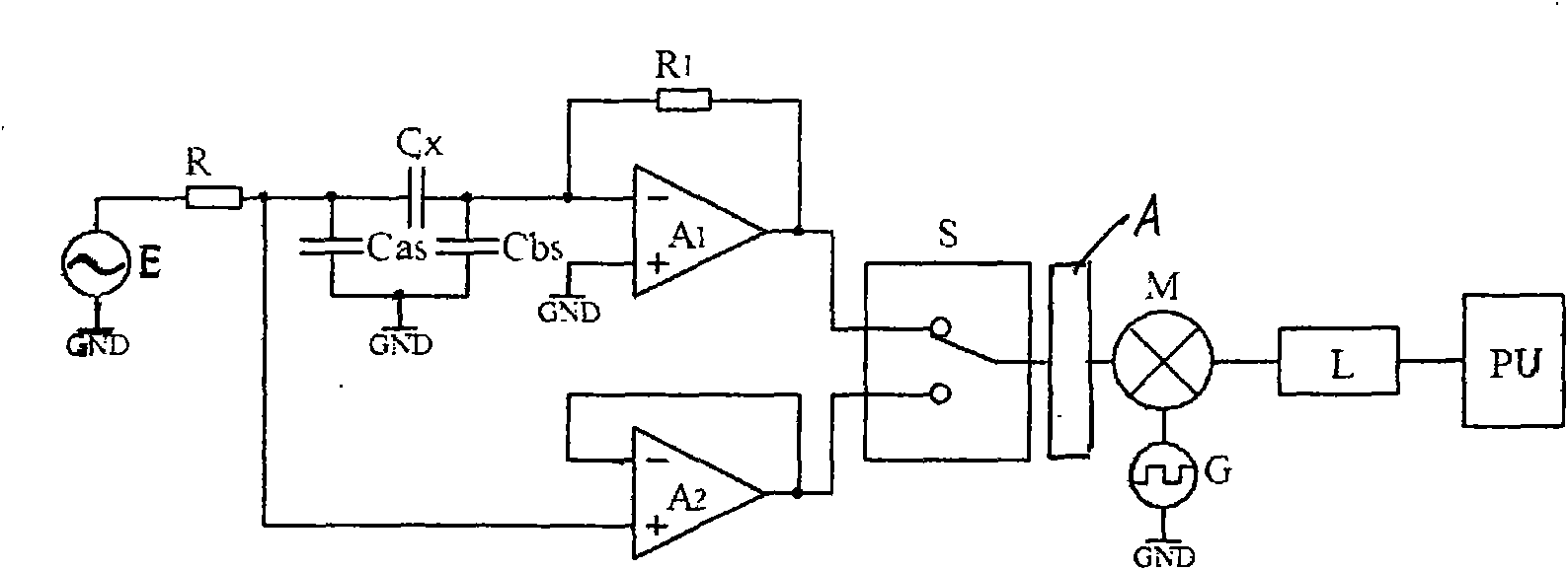
[0028] figure 1 It is based on the schematic diagram of the microcapacitance ratio measurement method. In the figure, E is the sine wave excitation voltage source, R is the current limiting resistor, and A 1 is the pre-op amplifier, R 1 is the feedback resistor of the pre-op amplifier, A 2 Is a voltage follower, A is an amplifying unit, G is a reference signal generator, M is a multiplier, L is a low-pass filter, S is a selection switch, and PU is a detection processing unit. The reference signal generator G generates two reference signals with the same frequency as the sine wave voltage excitation source E, and the phase difference of the two reference signals is 90°.

[002...


PUM


Abstract

The invention discloses a micro capacitance measurement method and a special device. The device is provided with a sine wave voltage driving source, a current-limiting resistor, a preposed operational amplifier, a feedback resistor, a voltage follower, an amplifying unit, a reference signal generator, a multiplying unit, a low-pass filter, a selective switch and a detection processing unit. The precision and the resolution of the method are high to the micro capacitance measurement.

Description

technical field [0001] The invention relates to electronic measurement technology, in particular to a microcapacitance measurement method. Background technique [0002] In the scientific research and manufacturing of semiconductor microelectronics, materials, biomedicine, and micro-electromechanical systems, the detection of weak capacitance is widely involved. Research and development of weak capacitance monitoring technology and devices has important practical significance. Microcapacitance measurement is basically divided into three types, namely, charge injection method (also known as charge and discharge method), AC excitation method, and AC excitation method with balanced capacitance. [0003] figure 2 It is the schematic diagram of the microcapacitance measurement based on the charge injection method. In the figure, E is the DC voltage source, Cx is the measured microcapacitance, Cas and Cbs are the stray capacitance of the measurement circuit, Z F is the feedback...

Claims


Application Information

Patent Timeline
13 Apr 2011
Publication
CN102012464A
IPC
G01R27/26
Inventors
彭建学; 季振明