Vehicle collision warning system based on optical communication

A technology for vehicle collision and communication system, applied in collision avoidance system, transmission system, electromagnetic wave transmission system and other directions, can solve the problem of not providing orientation indication, not having data communication function, etc.

Inactive Publication Date: 2011-04-13
EAST CHINA UNIV OF SCI & TECH
View PDF5 Cites 62 Cited by
  • Summary
  • Abstract
  • Description
  • Claims
  • Application Information

AI Technical Summary

Problems solved by technology

In addition to the installation position, these indicators only convey simple information, do not provide more specific orientation instructions, and do not have data communication functions

Method used


Image

  • Vehicle collision warning system based on optical communication
  • Vehicle collision warning system based on optical communication
  • Vehicle collision warning system based on optical communication

Examples


Embodiment Construction

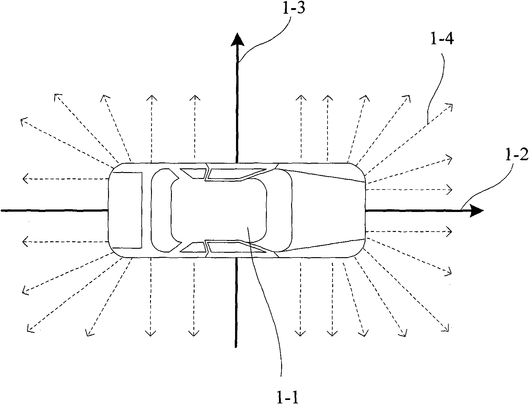
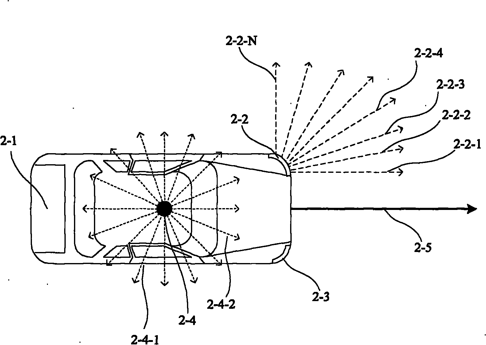
[0030] In the present invention, multiple (or multiple groups) LED light indicators with specific directionality and communication functions installed around or on the top of the vehicle can achieve similar figure 1 or figure 2 The effect shown in (2-4). exist figure 1 In , a virtual vehicle coordinate system parallel to the ground (road) plane is assumed with the longitudinal central axis (1-2) and transverse central axis (1-3) of the vehicle (1-1): the longitudinal central axis of the vehicle is the coordinate The transverse axis of the coordinate system (the direction of the vehicle head is the direction of 0°), and the transverse central axis of the vehicle is the longitudinal axis of the coordinate system. The angle between the light emitted by the LEDs placed around the vehicle (similar to the dotted line shown in 1-4, the arrow indicates the emission direction) and the central axis of the vehicle (1-2) is distributed from 0° to 360°. The setting principle is to refl...


PUM


Abstract

The invention relates to a vehicle collision warning system based on optical communication, which comprises optical indicators and optical detectors and is used for the safety monitoring and the information interaction among running vehicles. The optical indicators are distributed around or on the top of a vehicle and can transmit modulated optical signals in different directions, wherein the optical signals carry the angle indication information, mounting position information and other information of the vehicle which are corresponding to the optical signals, thereby forming optical antennae. The optical detectors mounted on another vehicle can detect optical pulse signals transmitted by a certain light emitting diode (LED) of the optical indicators and then extract the carried indication angle information, mounting position information and the like; and a processing unit of the optical detector analyzes and processes the information, estimates whether an abnormal running state exists based on the change rate of light indication angle, the change rate of light intensity and the like, and outputs the result to other systems of the vehicle by a controller.

Description

technical field [0001] The invention belongs to the technical field of intelligent transportation, and specifically relates to a method and device for measuring the relative running direction of short-distance vehicles by using an optical communication system, including a light indicator with a specific layout with an optical communication function and a light detector with an optical communication function device. Background technique [0002] In order to improve the safety performance of traffic, in addition to enhancing the electronic system of the body, more and more auxiliary electronic technologies are applied to the vehicle system, such as forward-looking infrared display, ultrasonic reversing radar, reversing camera, etc. In order to more actively detect obstacles in front of the vehicle, more advanced technologies such as automotive radar and laser scanners are gradually being used in vehicles. [0003] Among many technologies, the vehicle's collision prevention fu...

Claims


Application Information

Patent Timeline
Patent Type & Authority Applications(China)
IPC IPC(8): G08G1/16H04B10/10H04B10/11
Inventor 樊凌涛汪顺钱王平王胜飞西那
Owner EAST CHINA UNIV OF SCI & TECH
Why Eureka
Try Eureka