Medical suture needle

A suture needle and medical technology, applied in the field of medical suture needles, can solve problems such as the limit of hardness and bending strength, the weakening of the bending strength of the blade, and the inability to shorten the time, etc., to achieve high bending strength, easy penetration, and two-dimensional The effect of large second moments

Active Publication Date: 2011-04-13
MATSUTANI SEISAKUSHO CO LTD
View PDF10 Cites 8 Cited by
  • Summary
  • Abstract
  • Description
  • Claims
  • Application Information

AI Technical Summary

Problems solved by technology

[0012] Therefore, when the blade portion including the tip and the cutting edge starting from the tip is formed by grinding, the part with the highest hardness is ground off by grinding, and there is a problem that sufficient hardness cannot be obtained.
It can be said that this problem is caused by any of the cases where the part corresponding to the blade portion is roughly formed by pressing and then formed by grinding, or the case where the rough forming is not performed by pressing but is formed only by grinding. Even if the cross-sectional shape of the main body is an arbitrary shape, it will not change, and this problem will also occur.
[0013] In addition, in the above-mentioned conventional example in which the cross-section of the main body is triangular, both sides are punched surfaces, and one side is ground, the amount of grinding is increased in order to increase the sharpness, so there is a problem that the bending strength of the blade portion decreases. weak tendency
In terms of grinding time, it is necessary to first form the grinder into the shape of the grinding surface of the suture needle, so the current problem is that the time cannot be shortened as expected.
[0014] As described above, in the suture needle made of austenitic stainless steel having an elongated fibrous structure as a material, there is a problem that the blade including the sharp tip and the cutting edge formed from the tip There is a limit to the hardness and bending strength of the part

Method used


Image

  • Medical suture needle
  • Medical suture needle
  • Medical suture needle

Examples


Embodiment 1

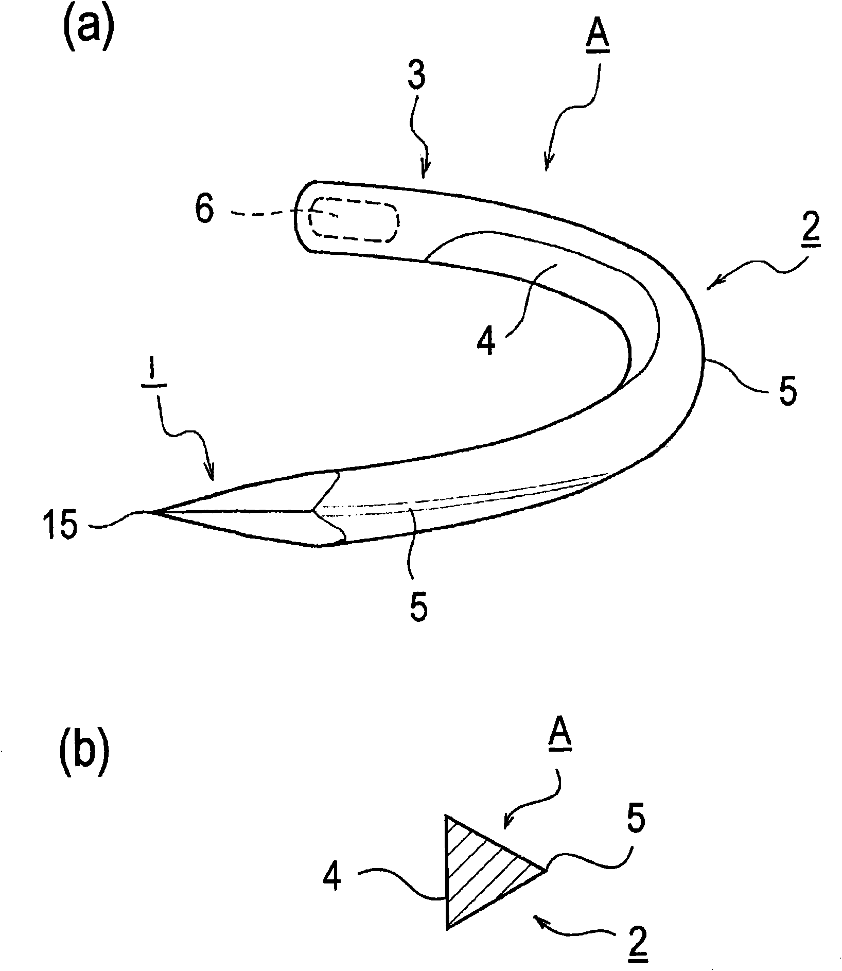
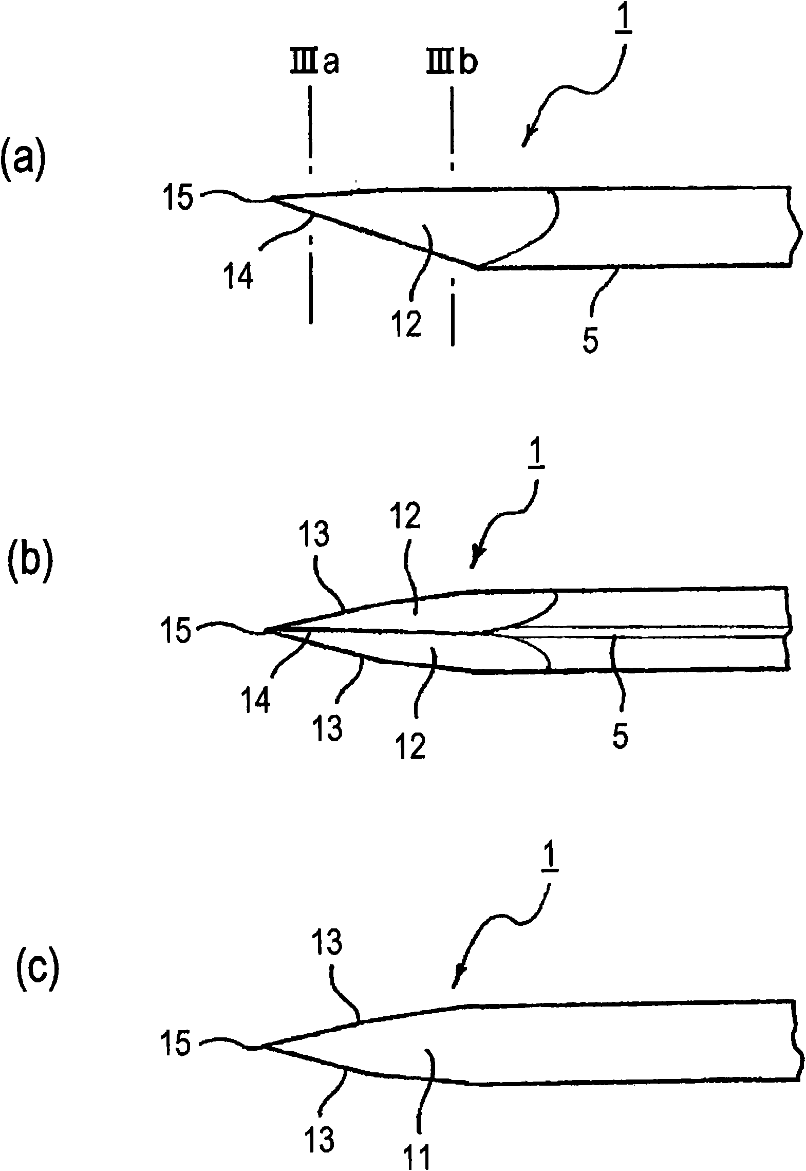
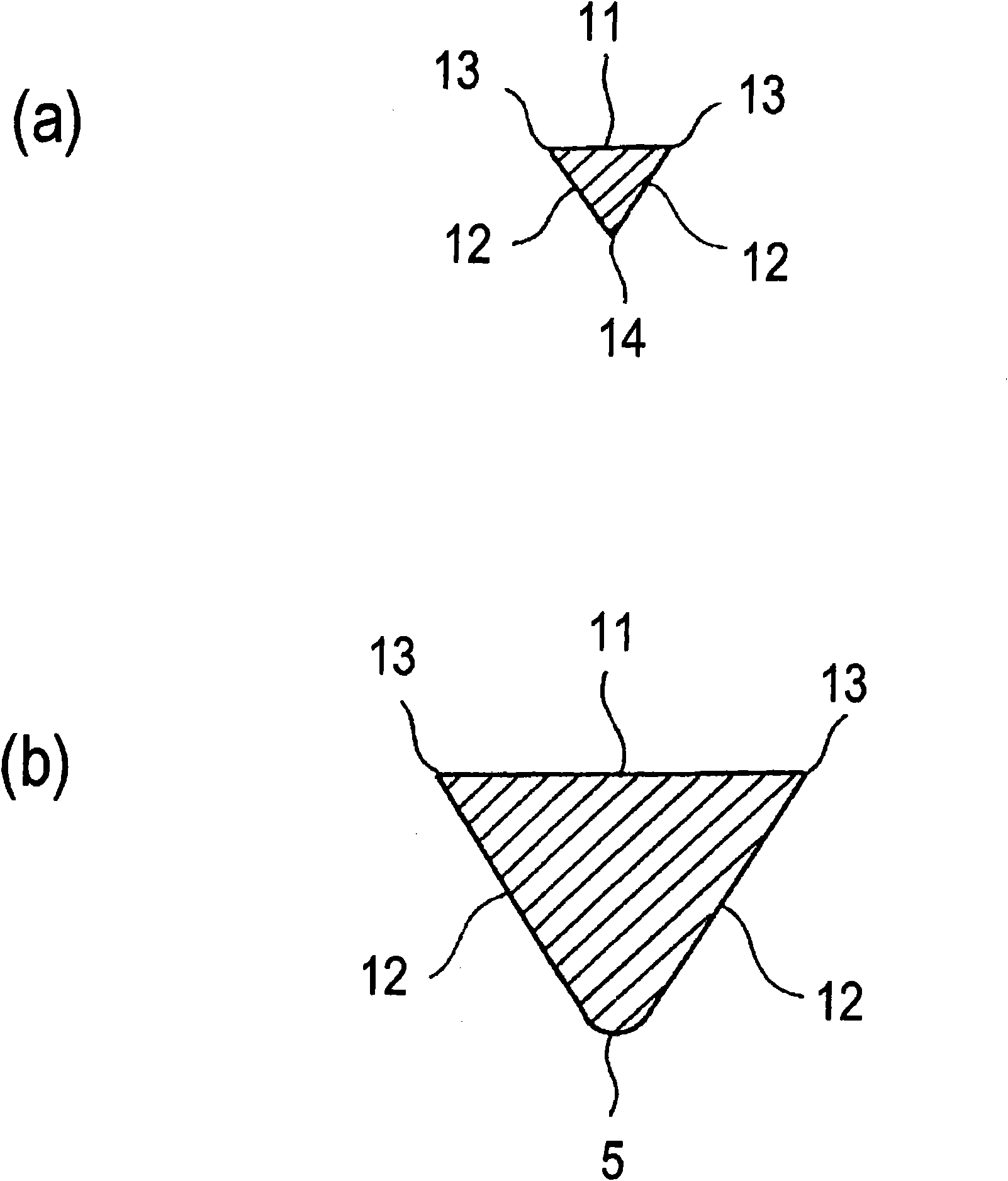
[0056] Next, the structure of the medical suture needle according to the first embodiment will be described with reference to the drawings. figure 1 It is a figure explaining the whole structure of the medical suture needle which concerns on this Example. figure 2 It is a figure explaining the structure of the front-end|tip part of the suture needle which includes a blade part. image 3 It is a figure explaining the cross-sectional shape of the tip part of a suture needle, and it is figure 2 The cross-sections of a and b.

[0057] First, through figure 1 The overall structure of the medical suture needle A will be described. The suture needle A is configured as a curved needle bent at a predetermined radius of curvature and bending angle. As mentioned above, the medical suture needle of the present invention is not limited to the curved needle of this embodiment, but may be a straight needle formed in a linear shape, and the overall shape is not limited.

[0058] In t...


PUM

PropertyMeasurementUnit
Vickers hardnessaaaaaaaaaa
hardnessaaaaaaaaaa
hardnessaaaaaaaaaa

Abstract

The goal is to provide a medical suture needle having, as the material, austenite stainless steel with a structure that is elongated in a fiber form while improving the hardness and flexural strength of the blade. A medical suture needle (A) is made of austenite stainless steel having a structure that is elongated in fiber form, and has a blade (1) and a shaft (2) with a triangular cross-sectional shape that is continuous with said blade (1). The blade (1) has cutting edges (13), at least one surface of which is formed by a pressed surface (11), and which are formed by the intersection of said pressed surface (11) with two sharpened surfaces (12), and a cutting edge (14) that is formed by the intersection of the two sharpened surfaces (12). The tip (15) where the various cutting edges (13) and (14) converge is positioned in the center of the pressed surface (11). Moreover, the cutting edges (13) formed by the intersection of the above pressed surface (11) with the two sharpened surfaces (12) are longer than the cutting edge (14) that is formed by the intersection of the two sharpened surfaces (12).

Description

technical field [0001] The present invention relates to a medical suture needle used for suturing an incised affected part, and more particularly to a medical suture needle with increased hardness at the needle tip. Background technique [0002] Medical suture needles (hereinafter referred to as suture needles) have a sharp tip at the front end and have a plurality of cutting edges (cutting edges) starting from the tip, suture needles that do not have a cutting edge and start from the tip A suture needle or the like having a substantially circular cross section. In addition, there are various specifications for shape and thickness setting, and various types of suture needles are provided for each specification. In addition, physicians appropriately select and use from these medical suture needles according to various conditions such as the living tissue or site to be sutured. [0003] In particular, a suture needle with a cutting edge has a cutting edge formed at a front e...

Claims


Application Information

Patent Timeline
Patent Type & Authority Applications(China)
IPC IPC(8): A61B17/06B21G1/00
CPCA61B2017/06071A61B17/06066B21G1/08A61B2017/0608B21G1/003B24B19/16
Inventor 栃村美正手塚智加藤一明
Owner MATSUTANI SEISAKUSHO CO LTD
Why Eureka
Try Eureka