Surgical system and surgical method for natural orifice transluminal endoscopic surgery (NOTES)

A technique of surgical operation and natural cavity, which is applied in the direction of surgical fixation nails, surgical cutting instruments, etc., and can solve the problems of large surgical injuries, long treatment period, and a lot of time and labor for patients.

Active Publication Date: 2011-04-13
坡埃库株式会社
View PDF5 Cites 16 Cited by
  • Summary
  • Abstract
  • Description
  • Claims
  • Application Information

AI Technical Summary

Problems solved by technology

[0015] Like this, although linear cutting/suture device and circular anastomosis device have taken various improvements and obtained continuous progress so far, although its constitution has realized from a natural opening (for example anus) will be used as the living body tube of circular anastomosis device The shaft assembly 1050 inserted into the main body is inserted into the living body tube, but it is necessary to use the thread to align the anvil after excision of the lesion of the living body intestine by the linear cutting/suturing device from the outside of the opening of the living body such as abdominal incision. The purse-bag banding near the cut end of the living body tube of the seat shaft 1104 and the trocar part, and the connection of the anvil part 1000 and the head 1061 throug...

Method used


Image

  • Surgical system and surgical method for natural orifice transluminal endoscopic surgery (NOTES)
  • Surgical system and surgical method for natural orifice transluminal endoscopic surgery (NOTES)
  • Surgical system and surgical method for natural orifice transluminal endoscopic surgery (NOTES)

Examples


Embodiment 1

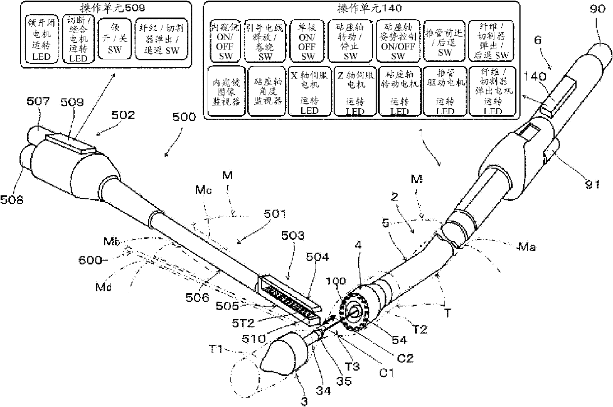
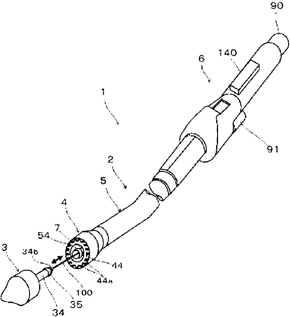
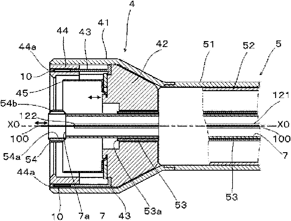
[0116] figure 1 It is a conceptual diagram showing the main configuration concepts of a NOTES surgical system according to an embodiment (Example 1) of the present invention, figure 2 It is a perspective view showing the main structural concept of the circular anastomosis device 1 of the NOTES surgical system of the first embodiment, image 3 yes figure 2 A longitudinal sectional view of the head 4, Figure 4 (a) is a longitudinal sectional view of the anvil portion 3, Figure 4 (b) is Figure 4 (a) P-P cross-sectional view, Figure 5 is a longitudinal sectional view of an anvil part 3 and a head 4 in a connected state, Image 6 yes means figure 2 A longitudinal sectional view of the main configuration concept of the operation unit 6, Figure 7 is a longitudinal sectional view of the anvil part 3 and the head 4 in a separated state, Figure 8 yes Image 6 The enlarged cross-sectional view of part E. In addition, the drawings here are all conceptual diagrams of th...

Embodiment 2

[0216] Figure 20 It is a conceptual diagram showing the main configuration concept of the NOTES surgical operation system according to the second embodiment of the present invention, Figure 21 It is a perspective view showing the main structural concept of the circular anastomosis apparatus 1A of the second embodiment, Figure 22 (a) means Figure 21 A longitudinal sectional view of the concept of the configuration of the anvil portion 3A, Figure 22 (b) means Figure 22 (a) R-R cross-sectional view, Figure 23 (a) means Figure 21 A longitudinal sectional view of the composition concept of the head 4A, Figure 23 (b) is Figure 23 (a) Q-Q cross-sectional view, Figure 24 yes means Figure 21 The longitudinal sectional view of the main configuration concept of the operation part, Figure 25 is in Figure 21 A longitudinal sectional view of the anvil portion 3A and the head portion 4A in a connected state during insertion into the living tube T, Figure 26 Is follo...


PUM


Abstract

Provided is a surgical system for NOTES by which surgical invasion can be reduced. A surgical system for NOTES comprising a circular anastomosis device (1) wherein an anvil part (3) attached to a guide electrical wire (100) is connected to a main body (2) to be inserted into body tract and then inserted into a body tract (T) from a natural orifice (Ma) and, after cutting off a lesion site (T3) inthe body tract with a pair of linear cutters (558, 559) of a linear cutter/stapler (500) having been inserted from a body cavity (Mb), the cut ends are anastomosed together for the repair.

Description

technical field [0001] The present invention relates to a surgical system and a surgical method for resecting the lesion of a living body tube and making the cut ends coincide with each other, and in particular to a method that saves the large-scale living body surgery such as laparotomy performed in the past so as to reduce the number of surgical operations. Surgical system and surgical method for traumatic natural orifice endoscopic surgery (NOTES). Background technique [0002] At present, in surgical operations such as resecting the lesion of living tubes such as the digestive tract and anastomosing the severed end into a circular tube shape, for example, the lesion of intestinal cancer has to be resected from the outside by incision of the abdomen, and then removed from the outside. A surgical procedure in which two severed ends are joined to each other. In recent years, the following surgical method has been proposed, which has been promoted into practical use quite e...

Claims


Application Information

Patent Timeline
IPC IPC(8): A61B17/115A61B17/072
CPCA61B17/115A61B17/07207A61B17/072A61B17/3205
Inventor 张惠生
Owner 坡埃库株式会社
Why Eureka
Try Eureka