Exhausting separating cleaning apparatus for combine harvester

A technology of combine harvester and cleaning device, which is applied in agricultural machinery and implements, threshing equipment, application, etc., can solve the problems of unsatisfactory cleaning effect, large size of grain cleaning mechanism, and high grain impurity rate, and achieves a simple structure. , The cleaning effect is good, and the grain contains less impurities.

Inactive Publication Date: 2011-04-20
湖南省双峰县湘源皇视电子有限公司
View PDF1 Cites 0 Cited by
  • Summary
  • Abstract
  • Description
  • Claims
  • Application Information

AI Technical Summary

Problems solved by technology

[0002] At present, most of the grain cleaning devices on combine harvesters that separate grains from weeds use an airflow sieve structure formed by a combination of multi-layer sieves and wind power devices. The airflow flows through the entire sieve surface from one end and blows to the other end. The reciprocating motion of the sieve drives the grains to separate from the weeds and fall out of the sieve holes, while the weeds continue to move to the other end under the action of the wind and are finally discharged. Outside the machine, in order to improve the separation effect, the general grain cleaning device has multi-layer sieves with different sieve holes. Together with the driving mechanism, the entire grain cleaning mechanism is bulky, accounting for one-third of the whole machine, and the power consumption is large, which needs to be improved.
[0003] In the small harvester, such as the technical solution disclosed in the patent document CN201029297, an exhaust fan is installed at the end of the grain outlet, and after the sieved grains fall into the grain receiving tank, the grains are pushed horizontally to the grain outlet by the transporting auger and freely fall , because the grain falling area is just located in the winnowing area of ​​the winnowing mechanism, the detritus impurities are removed by the winnowing mechanism suction air duct, but when the grain is blown out at the end of the grain outlet, the grain and miscellaneous debris are mixed together , in the process of falling, only part of the debris can be taken away by the upward draft, the impurity rate of the grain is still high, and the cleaning effect is not ideal

Method used


Image

  • Exhausting separating cleaning apparatus for combine harvester
  • Exhausting separating cleaning apparatus for combine harvester
  • Exhausting separating cleaning apparatus for combine harvester

Examples


Embodiment Construction

[0012] Below, the present invention will be further described in conjunction with the accompanying drawings.

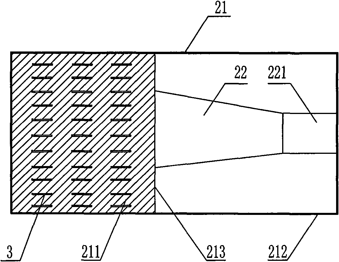
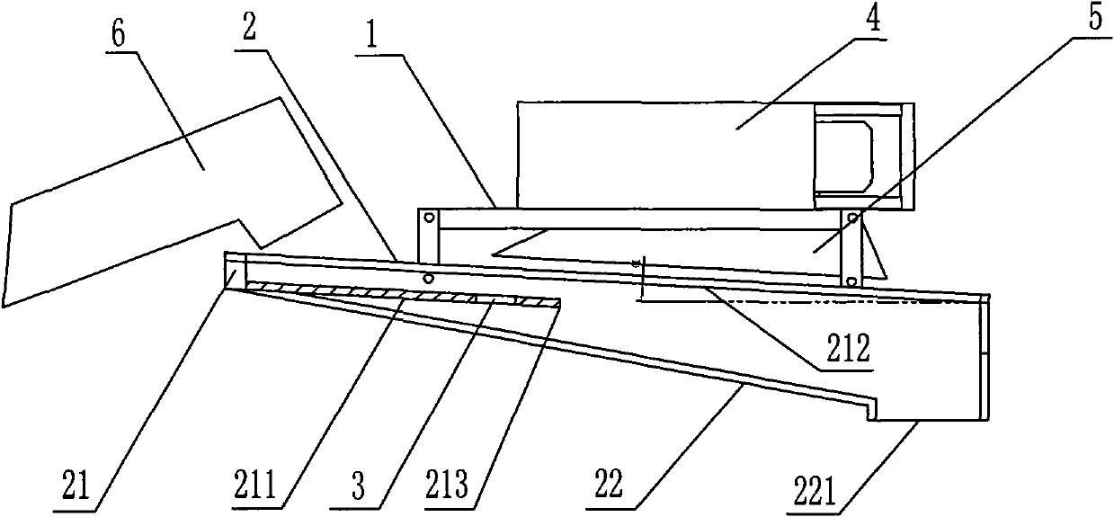
[0013] figure 1 An embodiment of the present invention is shown, a combined harvester ventilation separation type cleaning device, the sieve 2 is suspended on the frame 1, and is driven by an eccentric wheel mechanism to reciprocate and swing, the sieve 2 includes a sieve body 21 and a grain collection bin 22 , the bottom of the grain collection bin 22 is provided with a grain outlet 221, and the sieve body 21 includes a sieve bottom plate 211 and a square frame baffle plate 212. The wind cover 5 and the sieve bottom plate 211 are evenly distributed with sieve holes 3, the rear section of the sieve 2 is inclined downward, and the angle a between the square frame baffle plate 212 and the horizontal line is 3°.

[0014] The rear part of the sieve 1 is inclined downwards, and the grain materials in the threshing bin and the conveying mechanism 6 fall onto the sieve bott...


PUM


Abstract

The invention discloses an exhausting separating cleaning apparatus for combine harvesters. The invention comprises a reciprocating wobbling sieve driven by a driving mechanism installed on the frame. The sieve comprises a sieve body and a grain-gathering bin whose bottom is equipped with a grain exit. The sieve body comprises a sieve base plate and a square baffle plate. The front part of the sieve nest is equipped with a sieve base plate; the back part is equipped with a grain entrance and the upside is equipped with a drawing fan and a wind-gathering cover. The invention has a good cleaning effect that grains and weeds can be efficiently separated and the separated grains contain little foreign matters; the invention is of simple structure and low power consumption and occupies small space, thus is in favor of raising whole machine performance of harvesters.

Description

technical field [0001] The invention relates to a rice and wheat combine harvester, in particular to a cleaning device for separating grain and grass of the combine harvester. Background technique [0002] At present, most of the grain cleaning devices on combine harvesters that separate grains from weeds use an airflow sieve structure formed by a combination of multi-layer sieves and wind power devices. The airflow flows through the entire sieve surface from one end and blows to the other end. The reciprocating motion of the sieve drives the grains to separate from the weeds and fall out of the sieve holes, while the weeds continue to move to the other end under the action of the wind and are finally discharged. Outside the machine, in order to improve the separation effect, the general grain cleaning device has multi-layer sieves with different sieve holes. Together with the driving mechanism, the entire grain cleaning mechanism is bulky, accounting for one-third of the wh...

Claims


Application Information

Patent Timeline
Patent Type & Authority Applications(China)
IPC IPC(8): A01F12/44
Inventor 李源湘胡华锋
Owner 湖南省双峰县湘源皇视电子有限公司
Why Eureka
Try Eureka