Claw beam lifting mechanism for forging manipulator

A technology for forging operation and lifting mechanism, which is applied in forging/pressing/hammering machinery, manufacturing tools, forging/pressing/hammer devices, etc., can solve the complex structure of the synchronous link pin shaft assembly, difficult to install and maintain, and difficult to guarantee forgings Accuracy and other issues, to achieve the effect of convenient installation, adjustment and maintenance, low manufacturing cost and simple structure

Inactive Publication Date: 2011-04-20
SHENYANG HEAVY MACHINERY GROUP
View PDF6 Cites 44 Cited by
  • Summary
  • Abstract
  • Description
  • Claims
  • Application Information

AI Technical Summary

Problems solved by technology

When the synchronous link adopts the downward setting method, the working range of the synchronous link is always at the lower part of the line connecting the front and rear suspension points, that is to say, the synchronous link is always blocked by the side wall of the adjacent cart frame, and the synchronous link The rod pin assembly can only be installed and fixed in one direction on the inside, and the synchronous link pin assembly has a complex structure and is not easy to install and maintain
Due to the arc swing of the clamp rod lifting mechanism, the clamp head and the workpiece also move in an arc in the vertical direction, which is not easy to ensure the accuracy of forgings

Method used


Image

  • Claw beam lifting mechanism for forging manipulator
  • Claw beam lifting mechanism for forging manipulator
  • Claw beam lifting mechanism for forging manipulator

Examples


Embodiment Construction

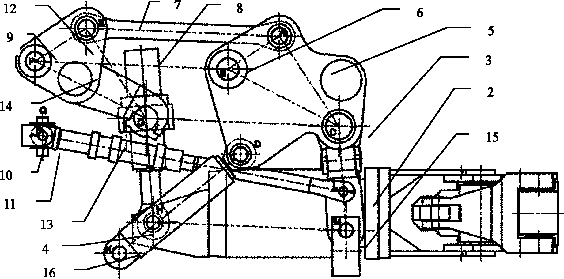
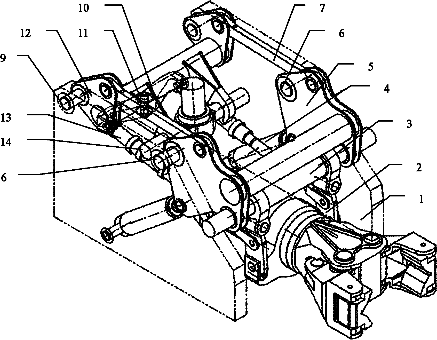
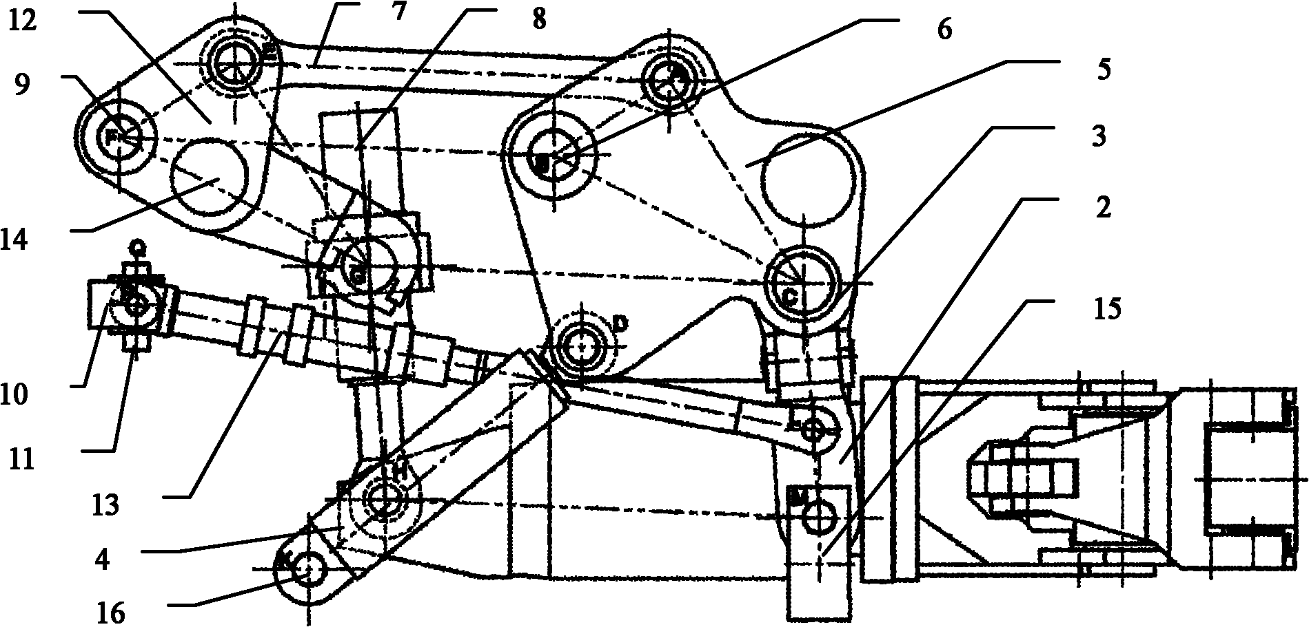
[0012] With reference to the accompanying drawings, the tong rod lifting mechanism of the forging manipulator is mainly composed of a front lifting component, a rear lifting component, a synchronous connecting rod 7, a lifting cylinder 4, a pitching cylinder 8 and a buffer component. The rear fixed shaft 9 in the lifting part and the lower end of the lifting cylinder 4 are hingedly connected with the cart frame 1 respectively, and the synchronous connecting rod 7 adopts the upper mode, that is, the working range of the synchronous connecting rod 7 is always within the lifting and tilting mechanism of the clamp rod 15 In the upper part of the line connected with the 6 hinge points of the front fixed shaft of the cart frame 1 and the 9 hinge points of the rear fixed shaft, the front ends of the two buffer cylinders 13 are respectively hinged with the two front lifting links 2, and the rear ends are respectively hinged on the compensation beam 10 At both ends, the middle part of t...


PUM


Abstract

The invention discloses a claw beam lifting mechanism for a forging manipulator, applied to forging industry. The claw beam lifting mechanism mainly comprises a front lifting part, a rear lifting part, a synchronous connector rod, a lifting cylinder, a pitching cylinder and a buffering part, a front fixing shaft in the front lifting part, a rear fixing shaft in the rear lifting part and the lower end of the lifting cylinder are respectively connected with a large machine frame through hinges, the synchronous connecting rod is arranged overhead and always moves in a range above a connecting line of a front fixing hinge point and a rear fixing hinge point of a claw beam lifting and pitching mechanism and the large machine frame, front ends of two buffering cylinders are respectively connected with tow front lifting connecting rods through hinges, the rear ends of the two buffering cylinders are respectively articulated with two ends of a compensating beam, and the middle part of the compensating beam is connected with the middle part of the large machine frame by a hinge through a beam fixing shaft. The claw beam lifting mechanism has novel and scientific design concept, reasonable stress application, high movement precision, simple structure, low manufacturing cost and is convenient to install, adjust and maintain. The invention not only reduces the manufacturing cost of the lifting mechanism under the condition of ensuring the movement precision, but also thoroughly solves the problems that the front fixing shaft and a shaft sleeve matched with the front fixing shaft are worn easily and a side plate of a machine needs to be thickened specifically.

Description

Technical field: [0001] The invention relates to a mechanism used in the technical field of forging processing equipment for manipulating the tong rod in the forging operation machine to perform forging actions such as lifting and tilting. Realize the mechanism for manipulating the tong rod to lift. Background technique: [0002] The forging manipulator is one of the basic tools for large-scale forging press processing, and it is a major equipment to realize the mechanization of forging production, and it is used in conjunction with the press. The current forging manipulators include wire rope hanging type, multi-rod mechanism combined type, etc. The wire rope hanging type forging manipulator has a small operating capacity and is used for small-scale forging, while the multi-bar mechanism combined forging manipulator has a large operating capacity and is used for large-scale forging. The forging manipulator is not only used to clamp forgings and billets for forging and pre...

Claims


Application Information

Patent Timeline
Patent Type & Authority Applications(China)
IPC IPC(8): B21J13/10
Inventor 卢崇劭梁音任云鹏
Owner SHENYANG HEAVY MACHINERY GROUP
Why Eureka
Try Eureka