
Lift-to-drag blending wing plate type vertical axis wind wheel

A vertical axis and wind wheel technology, applied in the field of wing-plate vertical axis wind wheels, can solve the problems of unfavorable wind flow, damage to the overall shape of the blade structure, and manufacturing difficulties, so as to improve the efficiency of wind energy conversion and improve the low operating speed. , Improve the effect of wind energy utilization characteristics

Inactive Publication Date: 2012-09-05
HENAN UNIV OF SCI & TECH
View PDF5 Cites 0 Cited by
  • Summary
  • Abstract
  • Description
  • Claims
  • Application Information

AI Technical Summary

Problems solved by technology

A typical lift-type wind rotor is a Darrieus type wind turbine. According to the shape of the blade, the Darrieus type fan has various forms such as Φ type, △ type, H type, Y type and ◇ type. It has high speed , large rotational inertia, simple structure, etc., but the starting torque is small and the starting performance is poor. When the tip speed ratio (blade tip speed / wind speed) is less than 3.5, it is difficult to start, and it needs to consume other energy to start the wind wheel
The typical drag-type wind wheel is the S-shaped Savonius type wind turbine, which has the advantages of simple structure, low cost, large turning torque, and good starting performance, but the speed and efficiency are low. The tip speed ratio is always less than 1
[0003] In view of the characteristics and deficiencies of the above-mentioned lift-type and drag-type vertical-axis wind rotors, there are some solutions in the prior art. For example, "a lift-drag complementary vertical-axis wind rotor" disclosed in Chinese Patent Publication No. A set of spiral resistance blades are installed inside the Φ-type lift wind wheel, and the lift type wind wheel and the resistance type wind wheel are assembled into a composite function wind wheel by mechanical combination to convert wind energy into mechanical energy. This type of wind wheel uses two The blades with different structures are arranged inside and outside, which is complex in structure and difficult to manufacture.
Another example is the "windmill for wind power generation" disclosed in Chinese Patent Publication No. CN100347440C, which is a part of the trailing edge of the lift vane (low Reynolds number and high lift coefficient) blade of the Darius type H-type wind wheel. The improved wing blade with the cross-sectional shape of "hollow comma" is cut off to achieve the comprehensive effect of the lift type wind rotor and the drag type wind rotor, but the cut part of the wind rotor blade damages the overall shape of the blade structure and is The underside of the airfoil forms a bluff surface that is not conducive to the flow of wind there

Method used


Image

  • Lift-to-drag blending wing plate type vertical axis wind wheel
  • Lift-to-drag blending wing plate type vertical axis wind wheel
  • Lift-to-drag blending wing plate type vertical axis wind wheel

Examples


Embodiment Construction

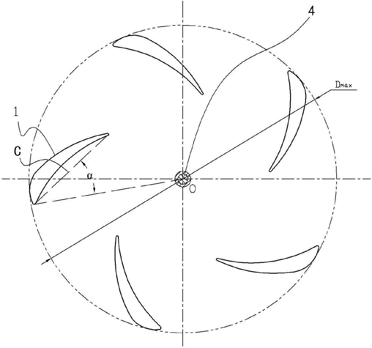
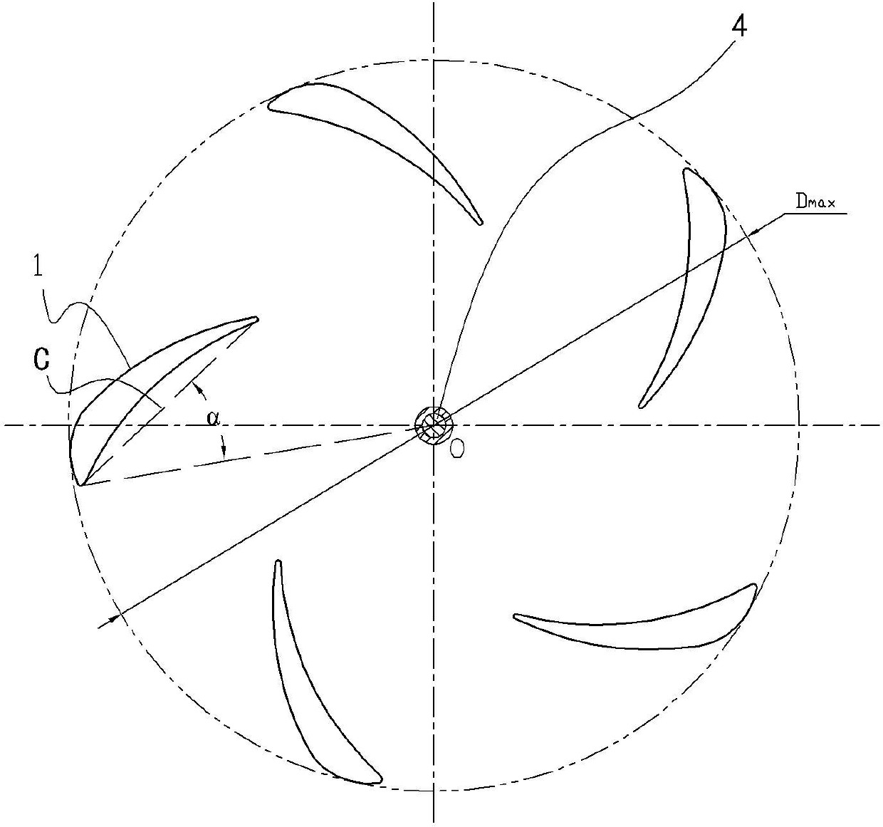
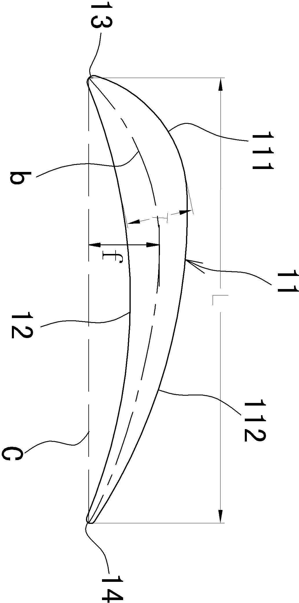
[0015] Such as Figure 1~3 As shown, the specific embodiment of the vertical axis wind wheel of the present invention includes a rotating shaft 4 and five blades 1 distributed along the circumference with the rotating shaft 4 as the center. On the upper cover plate 2 and the lower base plate 5 intersecting and fixedly arranged, the upper and lower ends of each blade 1 are fixed on the corresponding upper cover plate 2 and lower base plate 5 by bolts, and the wind force received by the blade 1 passes through the upper cover plate 2 And the lower base plate 5 is transmitted to the rotating shaft 4 . Each blade 1 is an airfoil-shaped lift-drag fusion wing plate whose height extension direction of the surrounding side is consistent with the axis of the rotating shaft 4 and whose cross-section is perpendicular to the rotating shaft 4. The surrounding side of the blade 1 is formed by a lift convex surface Cylinder 11, resistance concave cylinder 12, front transition arc cylinder 13...


PUM


Abstract

The invention discloses a lift-to-drag blending wing plate type vertical axis wind wheel, comprising a rotating shaft and a plurality of blades which are distributed along the periphery and take the rotating shaft as the center. Each blade is a lift-to-drag blending wing plate which is formed by integrally blending a lift convex surface and a resistance concave surface, and the combining part of the convex surface and the concave surface of the blade is provided with transition arc cylinder surfaces which can be matched mutually. The wind wheel combines the characteristics of drag and lift of the wind power utilization, has the advantages of low starting wind speed, fast speed increasing, high wind energy use ratio, low cost and the like, and is reliable in operation.

Description

technical field [0001] The invention relates to a vertical-axis wind rotor for wind power generation, in particular to a vane-type vertical-axis wind rotor with combined lift and drag functions. Background technique [0002] Wind energy is a clean, safe, and renewable green energy that is inexhaustible and inexhaustible. It has gradually become a new energy that is vigorously developed and utilized by countries all over the world. Wind turbines can be divided into two categories: horizontal axis wind turbines and vertical axis wind turbines. The structural feature of the horizontal axis wind turbine is that the rotation plane of the wind rotor is perpendicular to the wind direction, and the rotation axis is parallel to the ground. It is currently the most mature technology and the most widely used wind turbine. The vertical axis wind turbine is characterized by the fact that the rotation axis is perpendicular to the ground, and the rotation plane of the wind rotor is parall...

Claims


Application Information

Patent Timeline
Patent Type & Authority Patents(China)
IPC IPC(8): F03D3/06
CPCY02E10/74
Inventor 杨宗霄宋磊侯书奇王军邓瑞涛杨航航王隆彪
Owner HENAN UNIV OF SCI & TECH
Learn More