Control system and method of air compressor unit

A technology of air compressor unit and control system, applied in pump control, mechanical equipment, machine/engine, etc., can solve the problems of shortened life of air compressor and frequent start and stop of air compressor, so as to improve the service life and solve frequent problems The effect of start-stop and stable supply

Inactive Publication Date: 2011-04-20
SHANDONG IRON & STEEL CO LTD
View PDF6 Cites 12 Cited by
  • Summary
  • Abstract
  • Description
  • Claims
  • Application Information

AI Technical Summary

Problems solved by technology

[0005] In view of this, the embodiment of the present application provides an air compressor unit control system and method, by flexibly controlling the operation of the air comp

Method used


Image

  • Control system and method of air compressor unit
  • Control system and method of air compressor unit
  • Control system and method of air compressor unit

Examples


Embodiment 1

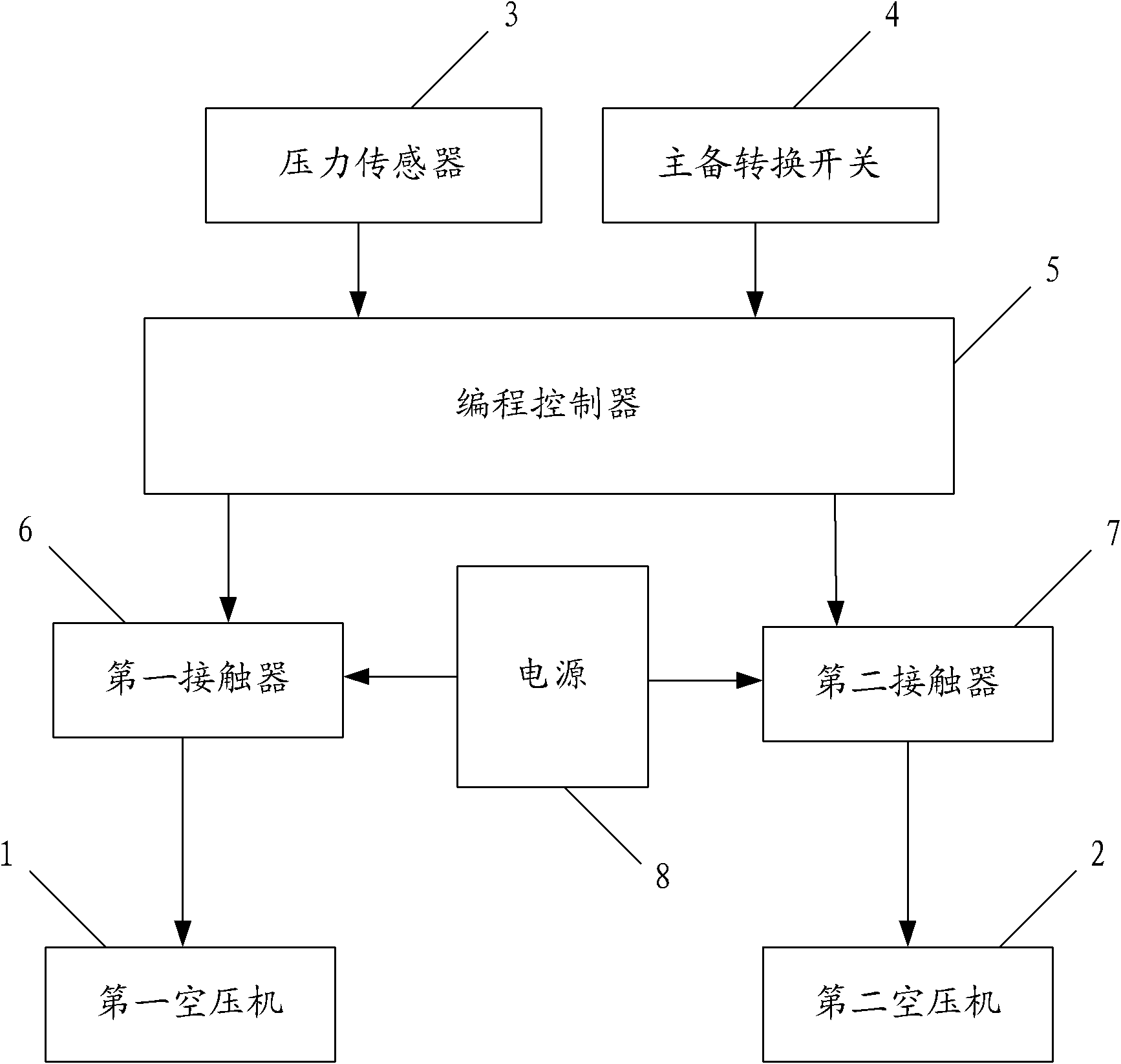
[0042] figure 1 This is a schematic structural diagram of an air compressor control system provided in an embodiment of this application.

[0043] Such as figure 1 As shown, the air compressor unit in the embodiment of the present application includes a first air compressor 1 and a second air compressor 2. The two air compressors are in a standby relationship with each other. The air compressor control system includes: a pressure sensor 3. Main / standby switch 4, programming controller 5, first contactor 6 and second contactor 7, in which: the first air compressor 1 is connected to the power supply 8 through the first contactor 6, and the second air compressor 2 is connected to the power supply 8 through the second contactor 7, the pressure sensor 3 and the main-standby switch 4 are connected to the programming controller 5, and the programming controller 5 is also connected to the first contactor 6 and the second contactor 7 respectively .

[0044] The pressure sensor 3 is install...

Embodiment 2

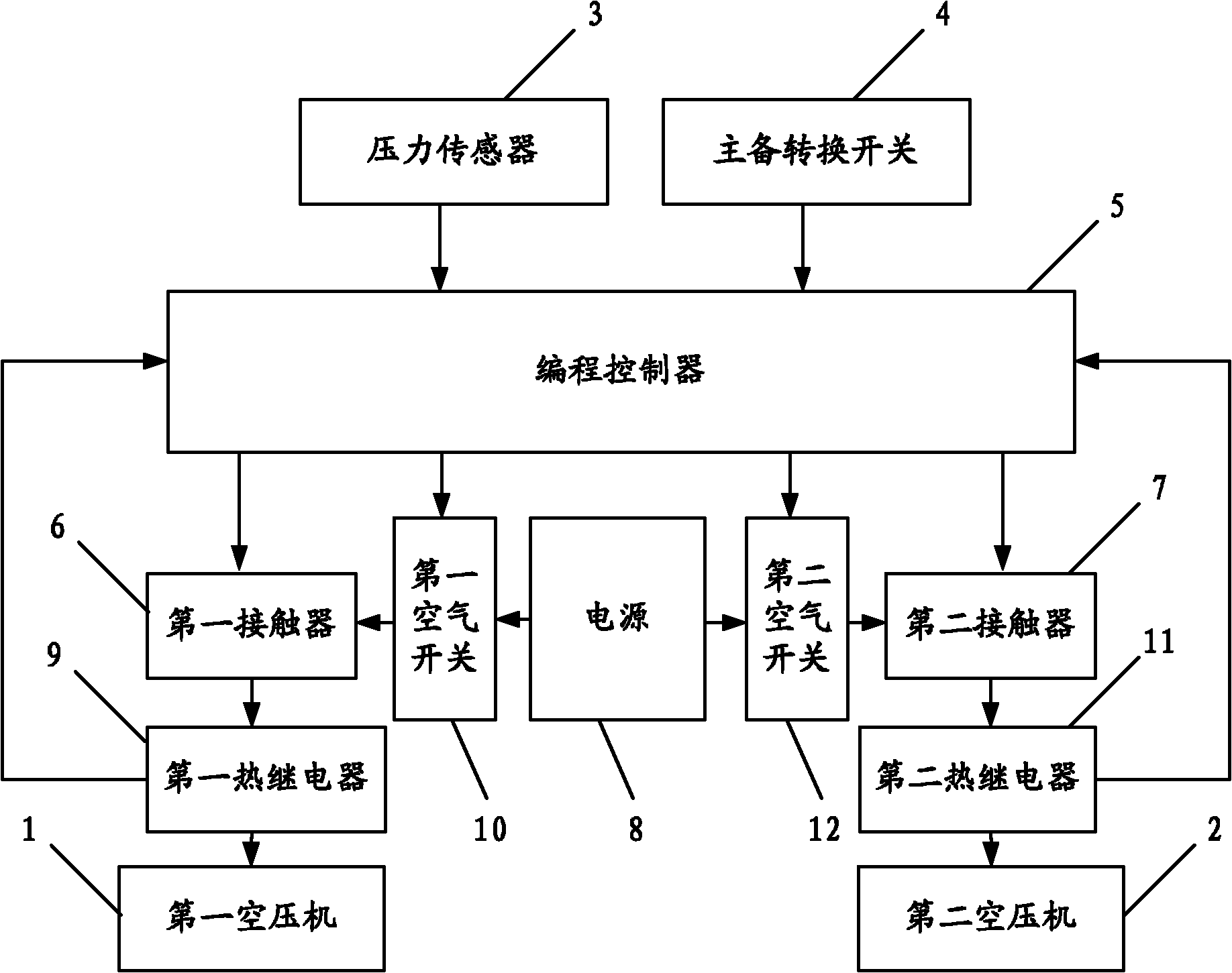
[0052] figure 2 This is a schematic structural diagram of another air compressor control system provided in an embodiment of this application.

[0053] In order to improve the avoidance of the air compressor being damaged due to overload during the operation process, thereby affecting the safety of the system operation, in the embodiment of the present application, the system may further include: a first thermal relay 9 and a first air switch 10 for Carry out overload protection for the first air compressor 1, where:

[0054] The first thermal relay 9 is connected between the first air compressor 1 and the first contactor 6, and is also connected to the programming controller 5 for detecting the input current of the first air compressor 1 and sending the overload current signal Send to programming controller 5;

[0055] The first air switch 10 is connected between the first contactor 6 and the power supply 8, and is connected to the programming controller 5. The programming control...

Embodiment 3

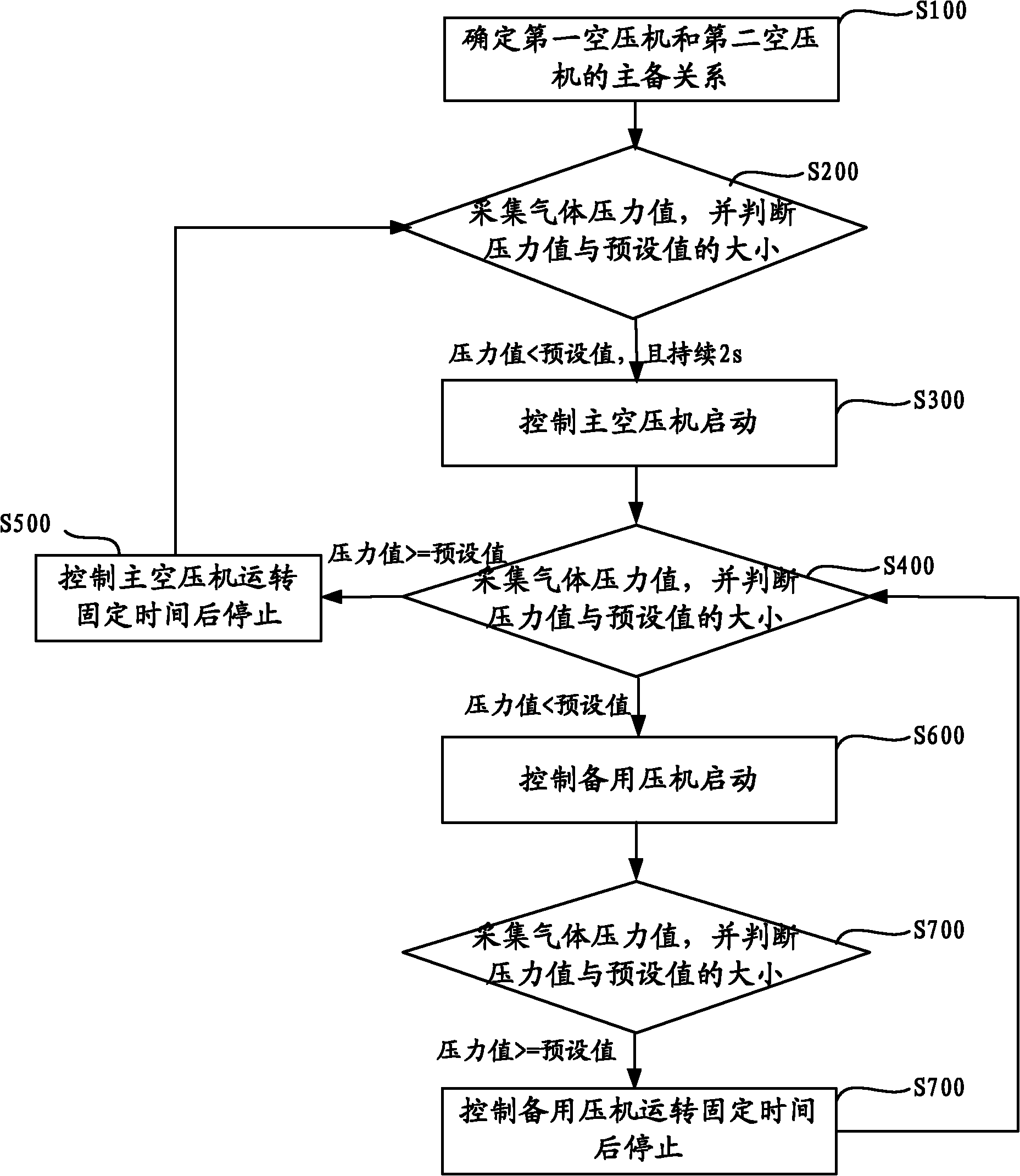
[0060] On the basis of the system provided in the first embodiment, the embodiment of this application also provides an air compressor control method, such as image 3 As shown, the flow diagram of an air compressor control method provided by an embodiment of this application.

[0061] Such as image 3 As shown, the method includes:

[0062] Step S100: Determine the main-standby relationship between the first air compressor and the second air compressor;

[0063] Step S200: Collect the pressure value of the gas inside the gas pipeline, and determine the magnitude of the pressure value and the preset value;

[0064] The collected pressure value is related to the gas transmission volume inside the gas pipeline, and the following operations are performed according to the judgment result: if the pressure value is greater than or equal to the preset value, step S200 is repeated; if the pressure value is lower than the preset value Set the value and continue for 2 seconds, then proceed to...


PUM


Abstract

The invention discloses a control system and method of an air compressor unit. The system comprises a pressure sensor, an active/standby conversion switch, a first contactor, a second contactor and a programming controller, wherein the pressure sensor is arranged in an air transportation pipeline and is connected with the programming controller; the active/standby conversion switch is connected with the programming controller and is used for switching active/standby relation of a first air compressor and a second air compressor; the first air compressor is connected with a power supply by the first contactor, the second air compressor is connected with the power supply by the second contactor; and the programming controller is connected with the first contactor and the second contactor and is used for controlling the operation of the first air compressor and the operation of the second air compressor according to the size of the pressure value collected by the pressure sensor and the size of the preset value. When the system operates, as delay time is set for starting and stopping of the active/standby air compressors and the time coordination is rational, the problem of frequent starting and stopping of the air compressors owning to great nitrogen pressure fluctuation can be solved and the service lives of the air compressors can be improved.

Description

Technical field [0001] This application relates to the field of air compressor control, in particular to an air compressor unit control system and method. Background technique [0002] In the metallurgical industry, air compressor units are mainly used as auxiliary blower safety devices. They are generally activated when the nitrogen pressure is lower than the preset value to increase the nitrogen pressure to ensure the safe and stable supply of cold air to the blast furnace. Normally, each air compressor unit is equipped with 2 air compressors. At present, the existing air compressor control device usually adopts the traditional electrical equipment control method, that is, a large number of master electrical appliances, control relays and contactors are used to realize the mutual backup function of two air compressors. [0003] In the factory, considering the cost factor, usually only one set of air compressors is equipped for each work area. Through the research of the existin...

Claims


Application Information

Patent Timeline
IPC IPC(8): F04B49/06
Inventor 李传记王新娣林佑祥岳长德关彦华鞠福道范纪涛冯惠平徐国强郝延雯
Owner SHANDONG IRON & STEEL CO LTD
Why Eureka
Try Eureka