Top gun applied to steel production

A top gun and steel technology, applied in the field of steel production, can solve the problems of large amount of oxygen blowing, large amount of wear on the surface of the hole, wear and water leakage of the pipe wall, etc., and achieve the effects of reducing corrosion of refractory materials, improving processing accuracy and prolonging service life.

Inactive Publication Date: 2011-04-20
MAANSHAN IRON & STEEL CO LTD
View PDF7 Cites 22 Cited by
  • Summary
  • Abstract
  • Description
  • Claims
  • Application Information

AI Technical Summary

Problems solved by technology

[0002] The top lance used in the production of electrical steel in the prior art has multiple functions such as combustion and heating, oxygen blowing decarburization, powder spraying and desulfurization, slag removal and slip removal, but in the actual use process, the top lance with this structure has many functions. The following problems: 1) Since the production of electrical steel adopts the "single-link" process, the amount of powder spraying and oxygen blowing per unit time is large, resulting in two problems: one is that the Laval throat aperture is too small, and the powder spraying 1. The oxygen blowing time is relatively long; the second is that the body of the gun head is TU2 oxygen-free copper, and the inner surface of the center tube is directly processed by the base material. The large amount of powder spraying causes a large amount of wear on the surface of the hole, which affects the service life of the gun head; 2) Due to the large spray hole angle design of the gun head, the refractory material in the vacuum tank will be eroded and washed during powder spraying and oxygen blowing, which will affect the service life of the vacuum tank; Section TU2 is made of oxygen-free copper plate curled and welded, with many weld seams, difficult plastic processing and welding, poor cylindricity and straightness, easy to rub against the expansion seal, causing pipe wall wear and leakage; 4) Top gun spare parts and repairs are completely dependent on Imported, the order cycle is long and the price is expensive

Method used


Image

  • Top gun applied to steel production
  • Top gun applied to steel production
  • Top gun applied to steel production

Examples


Embodiment Construction

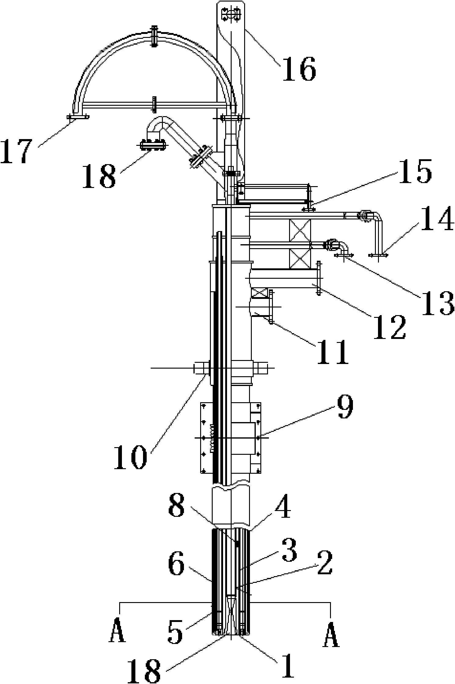
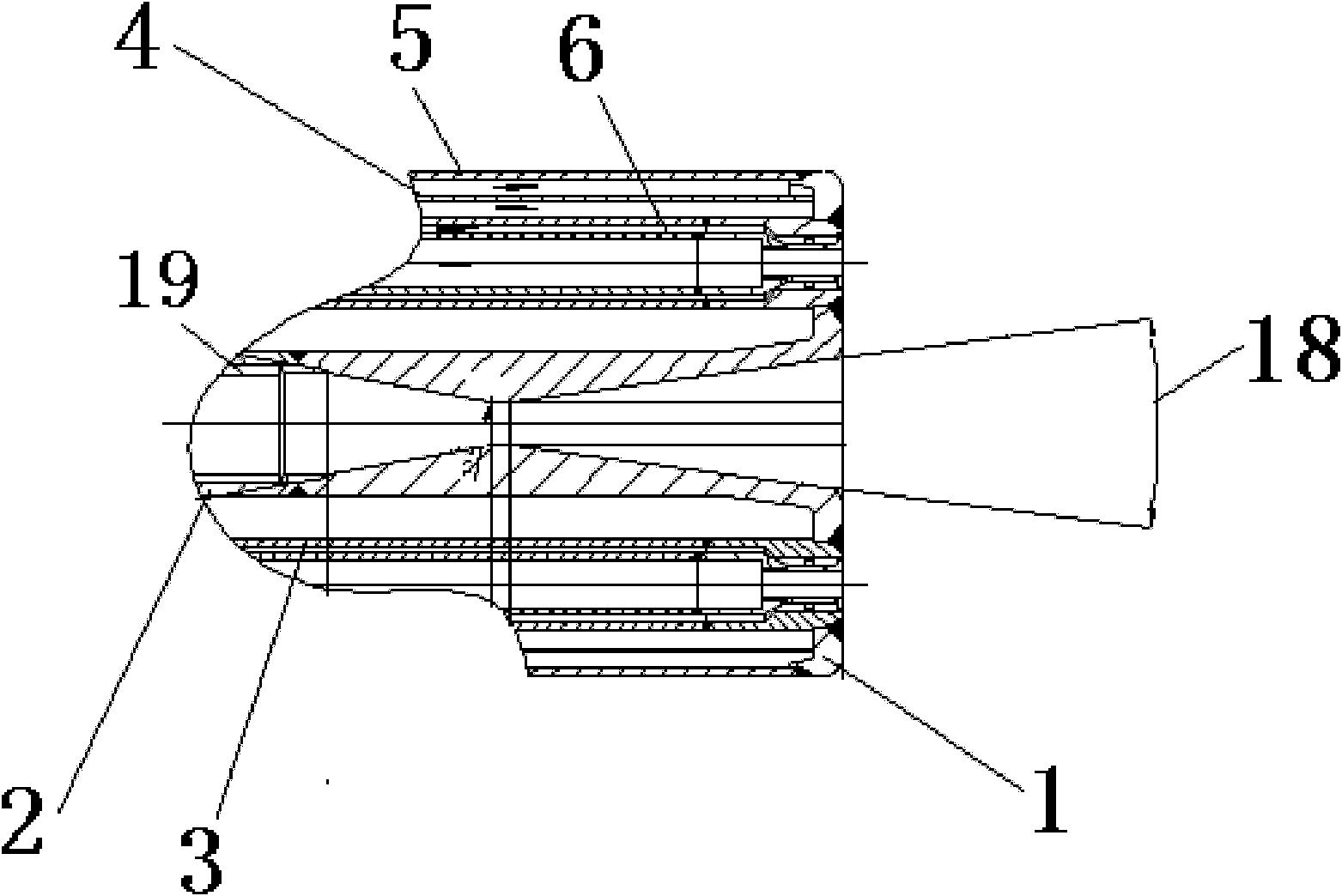
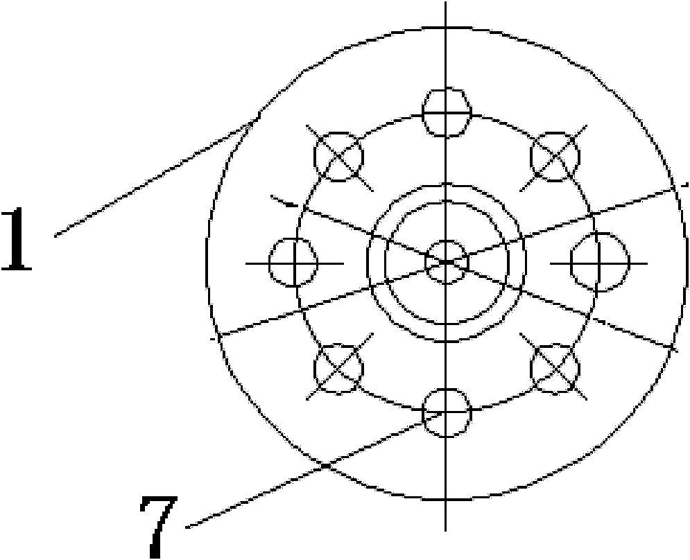
[0021] Below with reference to the accompanying drawings, through the description of the implementation examples, the specific embodiments of the present invention, such as the shape, structure, mutual position and connection relationship between each part, the role and working principle of each part, etc., will be further described. Detailed instructions:

[0022] as attached Figure 1-3 As shown, the present invention is a top gun applied to steel production, including a Laval gun head 1, a Laval gun head center pipe 2, a gas pipe 3, a water riser 4, an outer pipe 5, an oxygen pipe 6, and a flame detector Mounting hole 7, isolation device 8, gun body telescopic adjustment device 9, suspension device 110, cooling water outlet pipe 11, cooling water inlet pipe 12, combustion oxygen inlet pipe 13, gas inlet pipe 14, nitrogen gas inlet pipe 15, suspension Hanging device II 16, central oxygen inlet pipe 17, the Laval gun head 1 of the top gun used in steel production is set to T...


PUM

PropertyMeasurementUnit
thicknessaaaaaaaaaa

Abstract

The invention provides a top gun applied to steel production in the technical field of steel production. The top gun comprises a Laval gun head (1), a gun head center pipe (2), a fuel pipe (3), a marine riser (4), an outer pipe (5), an oxygen pipe (6), a flame detector installing hole (7), an isolation device (8), a gun body flexibility regulating device (9), a hanging device I (10), a cooling water outlet pipe (11), a cooling water inlet pipe (12), a combusting oxygen inlet pipe (13), a fuel inlet pipe (14), a nitrogen inlet pipe (15), a hanging device II (16) and a center oxygen inlet pipe(17), wherein the Laval gun head (1) of the top gun is made of TU2 oxygen-free copper materials, and a chromium electroplating hard layer is additionally arranged on the inner surface of the gun head center pipe (2). The top gun can prolong the service life of the gun head, can increase the powder injecting and oxygen blowing quantity in unit time, shorten the power injecting and oxygen blowing time, and lower the manufacture cost of the top gun.

Description

technical field [0001] The invention belongs to the technical field of steel production, and more specifically relates to a top gun used in steel production. Background technique [0002] The top lance used in the production of electrical steel in the prior art has multiple functions such as combustion and heating, oxygen blowing decarburization, powder spraying and desulfurization, slag removal and slip removal, but in the actual use process, the top lance with this structure has many functions. The following problems: 1) Since the production of electrical steel adopts the "single-link" process, the amount of powder spraying and oxygen blowing per unit time is large, resulting in two problems: one is that the Laval throat aperture is too small, and the powder spraying 1. The oxygen blowing time is relatively long; the second is that the body of the gun head is TU2 oxygen-free copper, and the inner surface of the center tube is directly processed by the base material. The la...

Claims


Application Information

Patent Timeline
Patent Type & Authority Applications(China)
IPC IPC(8): F27D3/18C21C5/46C21C7/072
Inventor 徐兆春张文全严学春俞玉璧
Owner MAANSHAN IRON & STEEL CO LTD
Why Eureka
Try Eureka