
Accelerator dosage monitoring device, correction method and method for monitoring offset of accelerator target spot P

A monitoring device and accelerator technology, used in dosimeters, material analysis using radiation, etc., can solve problems such as affecting the output dose of the accelerator and its statistical properties, not having too many advantages, affecting image quality, etc., achieving simple design and operation. Low cost and wide range of effects

Active Publication Date: 2011-04-20
NUCTECH CO LTD
View PDF0 Cites 12 Cited by
  • Summary
  • Abstract
  • Description
  • Claims
  • Application Information

AI Technical Summary

Problems solved by technology

However, the statistics of the data measured by these two methods are not much superior to the statistics of the data detected at the main beam, that is, the area commonly used for index testing; because the dose at the far corner is much lower than the dose at the central beam , especially for high-energy accelerators, this situation is particularly obvious; while the penetration ion chamber is made very thick, although it can improve the statistics of the monitoring dose data to a certain extent, it also affects the effective output dose of the accelerator and its statistics.
The statistics of the monitoring dose data will be passed to the latter when correcting the detection dose data, which will affect the image quality

Method used


Image

  • Accelerator dosage monitoring device, correction method and method for monitoring offset of accelerator target spot P
  • Accelerator dosage monitoring device, correction method and method for monitoring offset of accelerator target spot P
  • Accelerator dosage monitoring device, correction method and method for monitoring offset of accelerator target spot P

Examples


Embodiment Construction

[0032] The technical solutions of the present invention will be further specifically described below through the embodiments and in conjunction with the accompanying drawings. In the specification, the same or similar reference numerals designate the same or similar components. The following description of the embodiments of the present invention with reference to the accompanying drawings is intended to explain the general inventive concept of the present invention, but should not be construed as a limitation of the present invention.

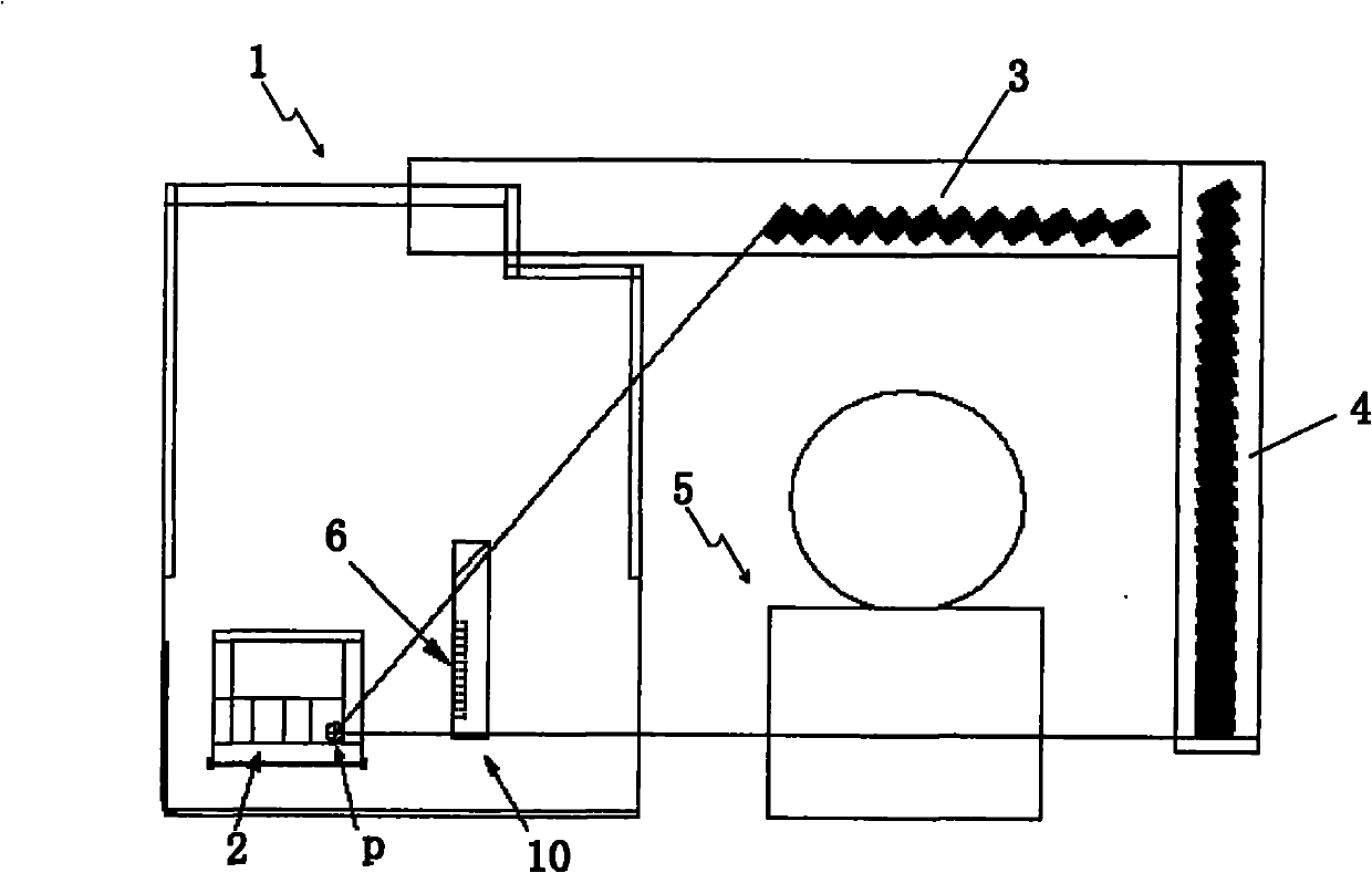
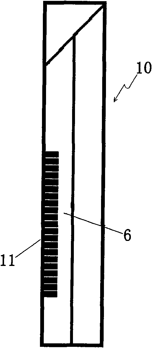
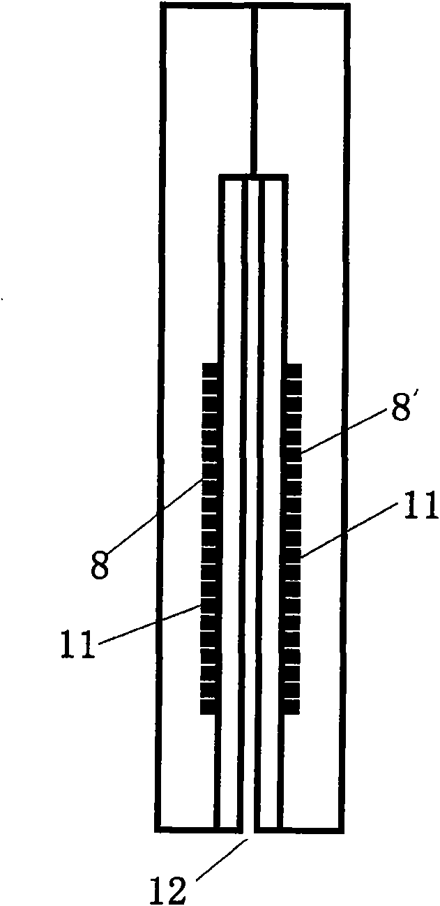
[0033] figure 1 It is a schematic diagram of an accelerator X-ray dose monitoring device in an X-ray radiation imaging system according to a specific embodiment of the present invention and an X-ray radiation imaging system having the above-mentioned accelerator X-ray dose monitoring device. figure 2 Side view showing the collimator set with detection detector set. image 3 It is a front view showing a collimator provided with two left and ...


PUM


Abstract

The invention discloses an accelerator X-ray dosage monitoring device in an X-ray radiation imaging system. The X-ray radiation imaging system comprises an accelerator X-ray source, a collimator for collimating X rays and a detection probe. The X-ray dosage monitoring device comprises an X-ray dosage monitoring probe, wherein X-ray dosage measured by the detection probe is corrected according to the X-ray radiation dosage monitored by the X-ray dosage monitoring probe. The X-ray dosage monitoring probe is arranged on at lease one side of a collimating slit of the collimator and is used for monitoring the dosage of the X rays radiated from an accelerator; and by changing the positions of dosage monitoring points, the dosage monitoring probe is arranged on the collimator, the monitoring probe is close to an accelerator target spot and the dosage rate of the accelerator received by the monitoring probe is high, so that data has high statistic properties. Simultaneously normal beams are not blocked, so the statistic properties of probe data of the detection probe are not reduced.

Description

technical field [0001] The invention relates to the field of accelerator X-ray container radiation imaging inspection. Specifically, the present invention relates to an accelerator X-ray dose monitoring device in an X-ray radiation imaging system and an X-ray radiation imaging system having the above-mentioned accelerator X-ray dose monitoring device. In addition, the present invention also relates to a method for correcting the X-ray dose of the accelerator in the X-ray radiation imaging system. In addition, the present invention also relates to a method for monitoring the deviation of the accelerator target point P in the X-ray radiation imaging system. Background technique [0002] Accelerator X-ray sources are the most important ray sources in the field of container radiation imaging inspection. The X-rays produced by the accelerator have high average energy, flexible output dose and safe radiation protection. However, the output dose is not very stable and needs to be...

Claims


Application Information

Patent Timeline
Patent Type & Authority Applications(China)
IPC IPC(8): G01T1/02G01N23/04
Inventor 阮明赵崑彭华
Owner NUCTECH CO LTD
Learn More