Optical fiber coupling connector

An optical fiber coupling and connector technology, which is applied in the field of embedded optical fiber coupling connectors, can solve problems such as affecting molding efficiency and product yield, difficult to pull out, damage, etc., to improve molding efficiency and product yield, and easy to assemble. , the effect of improving assembly efficiency

Inactive Publication Date: 2011-04-20
HONG FU JIN PRECISION IND (SHENZHEN) CO LTD +1
View PDF9 Cites 4 Cited by
  • Summary
  • Abstract
  • Description
  • Claims
  • Application Information

AI Technical Summary

Problems solved by technology

Since the blind hole 14 is an elongated hole, the ratio of its radial dimension to the axial dimension is relatively small. Therefore, the optical fiber coupling connector 10 is likely to cause the following problems: First, when molding, the molding core corresponding to the blind hole 14 The insert is relatively slender, so it is not easy to pull out the mold during demoulding, and it may even cause the insert of the mold core to be damaged or broken during the drawing process and block the blind hole 14, thereby affecting the molding efficiency and product yield; second, the assembly 3, it is difficult to adjust the distance between the optical fiber 12 and the optical lens 16, so it is difficult to obtain a better position of the port of the optical fiber 12 at the focal point of the optical lens 16

Method used


Image

  • Optical fiber coupling connector
  • Optical fiber coupling connector
  • Optical fiber coupling connector

Examples


Embodiment Construction

[0012] The present invention will be further described in detail below in conjunction with the accompanying drawings.

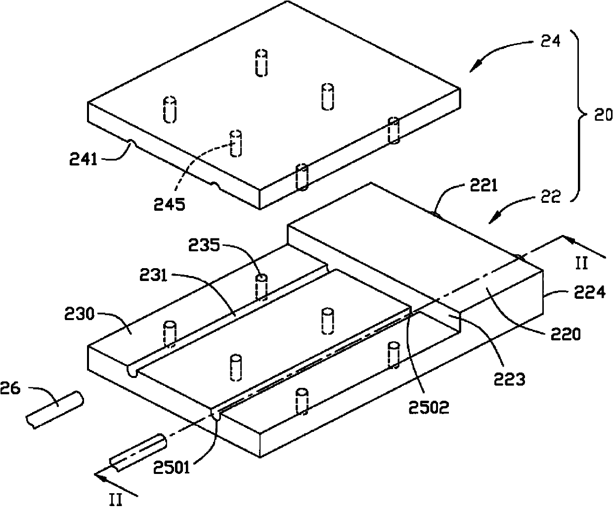
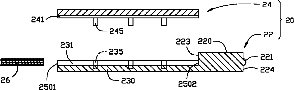
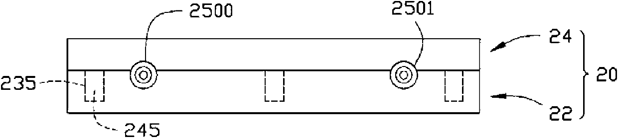
[0013] Please also refer to figure 1 and figure 2 , the first embodiment of the present invention provides a fiber coupling connector 20 for coupling an optical fiber 26 , which includes a body 22 and a cover 24 that are separated and detachably matched.

[0014] The body 22 has an optical coupling part 220 and a carrying part 230 . The optical coupling part 220 has a light incident surface 223 and a light exit surface 224 . The carrying portion 230 defines a first guiding groove 231 . The cover body 24 defines a second guiding groove 241 corresponding to the first guiding groove 231 .

[0015] Preferably, an optical lens 221 is disposed on the light emitting surface 224 , and the material of the optical lens 221 is the same as that of the optical coupling part 220 . The first guiding groove 231 extends toward the optical lens 221 .

[0016] The cover...


PUM


Abstract

The invention provides an optical fiber coupling connector which is used for connecting optical fibers in a coupling way and comprises a connector body and a cover which are matched detachably. The connector body comprises an optical coupling part and a bearing part, wherein the optical coupling part comprises an incident light face and an emergent light face, the bearing part and the cover are matched to form at least one optical fiber accommodating space which comprises a first port and the second port, and the insertion ends of the optical fibers are inserted in from the first port of the at least one optical fiber accommodating space and go out from the second port to directly butt against the incident light face of the optical coupling part.

Description

technical field [0001] The invention relates to an optical fiber coupling connector, in particular to a fitted optical fiber coupling connector. Background technique [0002] Optical fiber transmission has outstanding advantages such as wide frequency band, low loss, strong anti-interference ability, high fidelity and reliable working performance. As the cost of optical fiber continues to decrease, optical fiber has been more and more widely used in the field of communication. [0003] Optical fiber coupling connectors play an important role in optical fiber transmission, and the quality of optical fiber coupling connectors affects the efficiency of optical fiber transmission. see Figure 5 , which is a prior art solution of an optical fiber coupling connector. The optical fiber coupling connector 10 is an integral structure, which has a blind hole 14 for receiving the optical fiber 12 , and the blind hole 14 leads to an optical lens 16 at one end of the optical fiber coupl...

Claims


Application Information

Patent Timeline
Patent Type & Authority Applications(China)
IPC IPC(8): G02B6/38
CPCG02B6/3885G02B6/32G02B6/3652
Inventor 张仁淙
Owner HONG FU JIN PRECISION IND (SHENZHEN) CO LTD
Why Eureka
Try Eureka