Circuit breaker

A circuit breaker and airtight container technology, which is applied to high-voltage air circuit breakers, circuits, electrical components, etc., can solve the problems of the limit of the miniaturization of metal containers, the deterioration of the shielding cover 103, and the inability to ensure insulation, etc., so as to reduce the manufacturing burden, The effect of reducing the risk of consumption and reducing the number of manufacturing processes

Inactive Publication Date: 2011-04-20
HITACHI LTD
View PDF6 Cites 8 Cited by
  • Summary
  • Abstract
  • Description
  • Claims
  • Application Information

AI Technical Summary

Problems solved by technology

[0008] However, according to the structure of the above-mentioned Patent Document 2, the shield 103 is exposed to the arc, and as a result, the shield 103 is degraded and consumed, and there is a danger of insulation degradation.
[0009] In addition, according to the structure of Patent Document 2, since the shield case 103 is exposed to the arc, a high voltage is applied to this part, and therefore, insulation cannot be ensured unless a certain distance is maintained between the shield case 103 and the metal container. As a result, there is a limit to the miniaturization of metal containers
[0010] In addition, according to the structure of Patent Document 2, in order to suppress the deterioration and consumption of the shield 103 caused by exposure to the arc, it is necessary to use a noble metal material that makes the shield 103 less molten, and therefore, there is a problem that the manufacturing cost increases.

Method used


Image

  • Circuit breaker
  • Circuit breaker
  • Circuit breaker

Examples


Embodiment 1

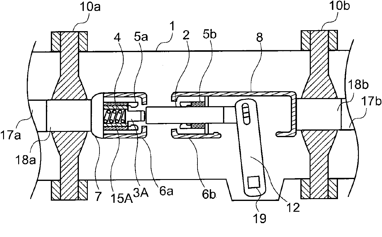
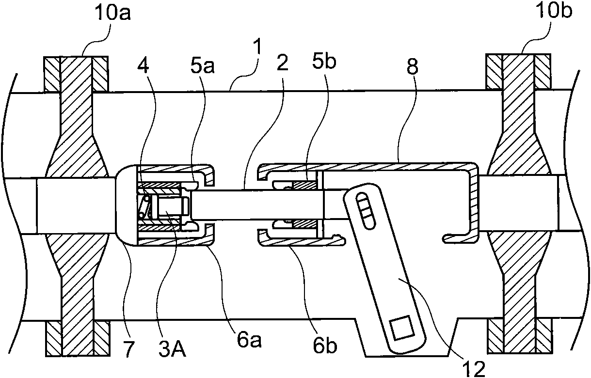
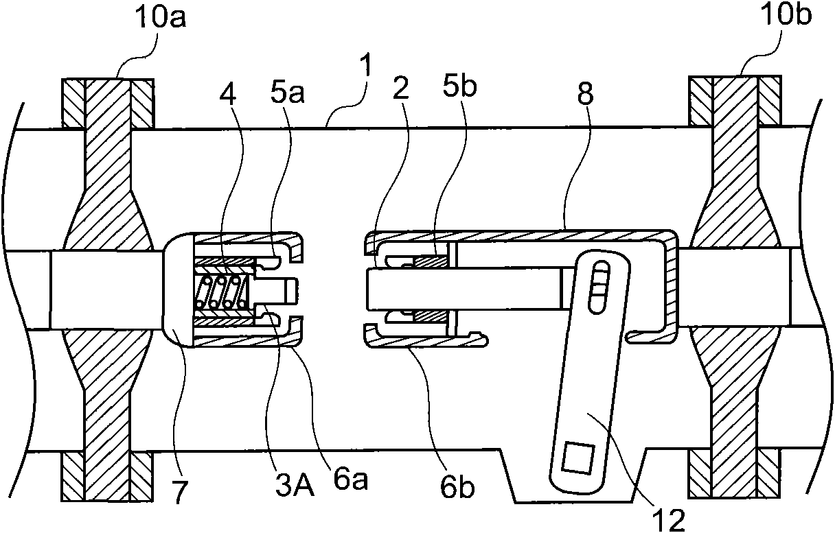
[0040] Figure 1-3 is a cross-sectional view of a circuit breaker as an embodiment of the present invention, figure 1 Indicates the state immediately after the circuit breaker is disconnected, figure 2 Indicates that the circuit breaker is closed, image 3 Indicates the disconnected state of the circuit breaker, Figure 4 yes figure 1 The enlarged cross-sectional view of the circuit breaker, Figure 5 (a) is figure 1 The front view of the fixed side seen from the movable side in the circuit breaker; Figure 5 (b) is figure 1 The front view of the movable side seen from the fixed side in the circuit breaker, Figure 6 is an enlarged cross-sectional view of the arcing contact.

[0041] The structure of the circuit breaker in Embodiment 1 is as follows: a metal container 1, a movable element 2, an arc contact 3A, a spring 4, a fixed side contact 5a, a movable side contact 5b, a fixed side shield 6a, a movable Side shield 6b, fixed side conductor 7, movable side cyli...

Embodiment 2

[0075] Below, based on Figure 12 Illustrates a second embodiment of the circuit breaker associated with the present invention, with figure 1 The same components are given the same reference numerals, and detailed descriptions are omitted.

[0076] Figure 12 It is an enlarged sectional view of the fixed side of the circuit breaker related to Embodiment 2. The characteristic of this structure is that no coil is provided on the arc contact, but a coil spring 16 is provided between the arc contact 3B and the fixed side conductor 7, and the coil spring 16 is provided between the arc contact 3B and the fixed side conductor 7. The spring 16 is characterized in that the current flows through the coil spring 16 when a surge occurs, and the coil spring 16 acts as an inductance that provides a surge reduction effect.

[0077] In this case, the support frame 15B for moving the arc contactor 3B in the axial direction is made of an insulating material so that no current flows. During th...

Embodiment 3

[0080] Below, based on Figure 13 Illustrates a third embodiment of the circuit breaker associated with the present invention, with figure 1 The same components are given the same reference numerals, and detailed descriptions are omitted.

[0081] Figure 13 Compared with the structure of the aforementioned second embodiment, the structure of the illustrated third embodiment is characterized in that the support frame 15B is omitted, and the arc contact 3C is supported only by the coil spring 16 .

[0082] By omitting the support frame 15B, the combined length of the arc contact 3C and the coil spring 16 related to the third embodiment can be set to be approximately equal to the length of the arc contact 3B related to the second embodiment. Compared with the structure of the second embodiment, the lengths of the arc contact 3C, the fixed-side contact element 5a, and the fixed-side shield 6a can be shortened. As a result, the axial length of the metal container 1 can be shor...


PUM


Abstract

The invention relates to a circuit breaker for improving insulating property while being capable of reducing the diameter of a metal container of the circuit breaker. The following components are arranged in the sealed container isolated by insulating clapboard of central conductor and filled with insulting gas: a fixed side conductor installed on the central conductor of insulating clapboard of one side; a fixed side contact element connected with the fixed side conductor; an electric arc contact terminal installed on the inner side of the fixed side contact element; a fixed side shielding hood allocated to surround the fixed side contact element; a movable element in contact with the fixed side contact element and the electric arc contact terminal and firstly cut off from the fixed side contact element before being turned off with the electric arc contact terminal; a spring driving the electric arc contact terminal to move along the axial direction if the movable element is cut off; and a following device of supporting framework; besides, a serially connected inductor provided with coil part or magnet is inserted between an electric arc extinguishing part of the electric arc contact terminal and the fixed side conductor.

Description

technical field [0001] The present invention relates to a circuit breaker, in particular to a circuit breaker arranged in a substation or a switching station. Background technique [0002] In a switching device such as a circuit breaker or a switch that constitutes a gas-insulated switching device, there is a high possibility of high-frequency switching surges during switching, especially for circuit breakers with relatively slow switching speeds. Reburning arcs are prone to occur during operation. [0003] The surge caused by the re-ignition arc during the switching operation of the circuit breaker ranges from several MHz to tens of MHz, and its frequency is high, and its frequency of occurrence is also high. Moreover, since such a surge is a steep overvoltage with a high frequency of occurrence, Therefore, the problem of low insulation performance of the circuit breaker is likely to occur. [0004] As one of the countermeasures for suppressing the generation of the surge...

Claims


Application Information

Patent Timeline
Patent Type & Authority Applications(China)
IPC IPC(8): H01H33/04H01H33/16
Inventor 加藤逹朗六戶敏昭篠原亮一
Owner HITACHI LTD
Why Eureka
Try Eureka