Communication system used for underground machinery equipment

A technology for mechanical equipment and communication systems, applied in the field of communication systems, can solve problems such as inconvenience and inconvenience of wiring, and achieve the effect of saving costs

Inactive Publication Date: 2013-05-01
SHANGHAI HUAXING DIGITAL TECH
View PDF3 Cites 0 Cited by
  • Summary
  • Abstract
  • Description
  • Claims
  • Application Information

AI Technical Summary

Problems solved by technology

[0004]①Wireless communication and PHS network are adopted as a whole: All data and voice transmission of these two schemes rely on wireless links, and the underground roadway is not as wide as the ground, and the passageway is curved More, the wireless signal is easily disturbed and unstable in the non-line-of-sight environment; multiple wireless relays need to be arranged, which increases the cost of later maintenance;
[0005]② Laying of dedicated CAN communication cable: 1.5mm cross-section twin-core twisted-pair cable about 6.8 yuan / meter, cable required per kilometer The cost is about 7,000 yuan, and it will increase with the advancement of equipment work. When the communication distance exceeds 7km, a CAN relay needs to be added. The cost of the entire system is quite expensive, which increases the cost of excavation;
[0006]③Telephone line transmission based on 52K Modem: Borrowing the original telephone line in the mine, the cost is the cheapest, but it cannot realize the simultaneous transmission of voice and data. The underground phone cannot be used, and the data transmission must be stopped when making a call. It is not suitable for use based on safety and convenience considerations
[0007] In addition, because the underground coal mining machine and other equipment are moving, and the tail of the coal mining equipment needs to lay a hydraulic support of about 100 meters, it is inconvenient to connect wires, so The above schemes ② and ③ are all wired connections, and it is inconvenient to use them here

Method used


Image

  • Communication system used for underground machinery equipment

Examples


Embodiment 1

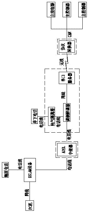
[0021] Embodiment one: see figure 1 As shown, a communication system for underground mechanical equipment includes a wireless transmission part and a wired transmission part. The main controller of each device transmits data to the signal conversion device through the wireless transmission part, and the signal conversion device passes through the wireless transmission part. The wired transmission part is connected with the telephone set and data receiving equipment on the ground;

[0022] The wireless transmission part: includes a protocol converter with a wireless function, the protocol converter is connected with the main controller of each device via the CAN bus, and connected with the serial port server with the wireless data transmission function via the wireless network.

[0023] The wired transmission part: the signal conversion device includes a modem, a serial server with wireless data transmission function and an electrical isolation barrier, the serial server...


PUM


Abstract

The invention discloses a communication system used for underground machinery equipment. The communication system is characterized by comprising a wireless transmission part and a wire transmission part, wherein a master controller of each piece of equipment is connected with a signal conversion device through the wireless transmission part and is connected with ground equipment through the wire transmission part; the signal conversion device comprises a modem and a serial server; the serial server receives a data signal and sends the data signal to the modem; an underground telephone is connected with the modem through a telephone wire; and the modem is connected with an asymmetrical digital subscriber loop (ADSL) repeater through the telephone wire, is connected with digital subscriber line access multiplexer (DSLAM) equipment, and is connected with ground telephone and data receiving equipment finally. By combining wireless and wired modes, the communication system realizes two-waytransmission of voice and data with the help of an original telephone wire without mutual influence, greatly reduces system cost, and improves communication safety.

Description

technical field [0001] The invention relates to a communication system, in particular to a communication system for underground mechanical equipment. Background technique [0002] Underground roadheaders, coal shearers and other equipment work in mines below the ground, and generally there is no mobile network coverage. The distance between the underground operation surface of some equipment and the ground can reach 10km. In order to realize the monitoring of the underground operation machinery, it is necessary to solve the communication problem. [0003] Theoretically speaking, there are many ways to achieve it, such as: adopting wireless communication as a whole, laying dedicated CAN communication cables, telephone line transmission based on 52K modem, PHS network, etc. These main communication methods are compared: [0004] ①Wireless communication and PHS network are adopted as a whole: All data and voice transmission of these two schemes rely on wireless links. The unde...

Claims


Application Information

Patent Timeline
Patent Type & Authority Patents(China)
IPC IPC(8): H04M11/06
Inventor 戴晴华袁爱进郭长城
Owner SHANGHAI HUAXING DIGITAL TECH
Why Eureka
Try Eureka