Hydraulic elastic workholder device

A fixture device, hydraulic technology

Inactive Publication Date: 2011-04-27
常州市科邦精密数控机械有限公司
View PDF0 Cites 5 Cited by
  • Summary
  • Abstract
  • Description
  • Claims
  • Application Information

AI Technical Summary

Problems solved by technology

[0003] The present invention provides a hydraulic elastic fixture device, wh

Method used


Image

  • Hydraulic elastic workholder device
  • Hydraulic elastic workholder device
  • Hydraulic elastic workholder device

Examples


Embodiment Construction

[0014] The present invention will be further described below in conjunction with accompanying drawings and embodiments.

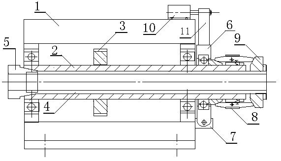
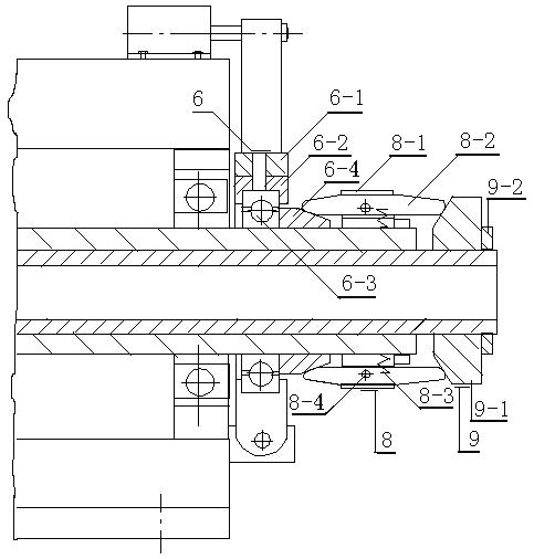
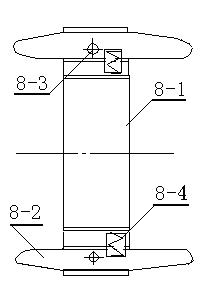
[0015] Examples, see attached figure 1 , the figure is a schematic diagram of the device of the present invention, including a power head 1, a main shaft 2, a gear 3, a hollow shaft 4, a chuck 5, a shift fork 6, a rocker seat 7, a clutch 8, a push block 9, a hydraulic cylinder 10, The rocker 11; the main shaft 2 is installed in the bearing hole of the power head 1 with a pair of rolling bearings, the gear 3 is fixedly installed on the main shaft 2 and connected with the transmission mechanism to make the main shaft 2 rotate, and the hydraulic cylinder 10 is fixedly installed on the box of the power head 1 Above, its piston rod is movably connected with the rocker 11, the rocker 11 is movably connected with the shift fork 6 and the clutch 8 through the rocker seat 7, and the clutch 8 is movably connected with the push block 9 on the hollow shaft 4 with its c...


PUM


Abstract

The invention relates to a hydraulic elastic workholder device solving the problem of automatic loading of axle workpieces. The device comprises a power head, a spindle, a gear, a hollow axle, a chuck, a poking fork, a rocker seat, a clutch, a pushing block, a hydraulic cylinder and a rocker, wherein the hydraulic cylinder is fixedly installed on the power head, a piston rod of the hydraulic cylinder is movably connected with the poking fork through the rocker, the rocker is movably connected with the rocker seat through a pin and is connected with a sliding cone sleeve through a rolling bearing of the poking fork on the spindle in a sliding way, the clutch is sleeved on the spindle through inside threads, is fixedly matched with the spindle, is in contact with a sliding cone through a clutch claw at the left side, and is in contact with the pushing block at the right side, and the hydraulic cylinder is electrically connected with a PLC (Programmable Logic Controller) control device through an electromagnetic valve. The device has the advantages of agile action, reliable clamping, accurate location, automatic reset and the like.

Description

technical field [0001] The invention relates to a clamp device, in particular to a hydraulic elastic clamp device. Background technique [0002] CNC machine tools play a very important role in processing lines or machining centers. Therefore, the functional requirements for CNC machine tools are becoming more and more extensive. In particular, higher requirements are put forward for the automatic loading and unloading fixture devices of various workpieces. In order to adapt to the automatic loading and unloading of shaft workpieces, a hydraulic elastic clamping device is designed, which has the characteristics of quick action, reliable clamping, accurate positioning, and automatic reset. Contents of the invention [0003] The invention provides a hydraulic elastic clamp device, which solves the problem of automatic loading and unloading of shaft workpieces. [0004] A specific embodiment of the present invention is that the device includes a power head, a main shaft, a g...

Claims


Application Information

Patent Timeline
IPC IPC(8): B23Q3/12B23Q5/04B23B19/02
Inventor 周小明周东波
Owner 常州市科邦精密数控机械有限公司
Why Eureka
Try Eureka