Differential pressure power pressure booster

A supercharger and power technology, which is applied to machines/engines, mechanical equipment, liquid variable capacity machinery, etc., can solve the problems of insufficient pressure and difficult exploitation of low-yield and low-pressure gas fields, so as to protect formation pressure, save production costs, and use handy effect

Active Publication Date: 2011-04-27
PETROCHINA CO LTD
View PDF10 Cites 32 Cited by
  • Summary
  • Abstract
  • Description
  • Claims
  • Application Information

AI Technical Summary

Problems solved by technology

Solve the problem that low-production and low-pressure gas fields are difficult to exploit due to insufficient formation pressure of low-production and low-pressure gas wells

Method used


Image

  • Differential pressure power pressure booster
  • Differential pressure power pressure booster
  • Differential pressure power pressure booster

Examples


Embodiment 1

[0031] Embodiment 1: Taking a differential pressure power booster as an example, the present invention will be further described in detail.

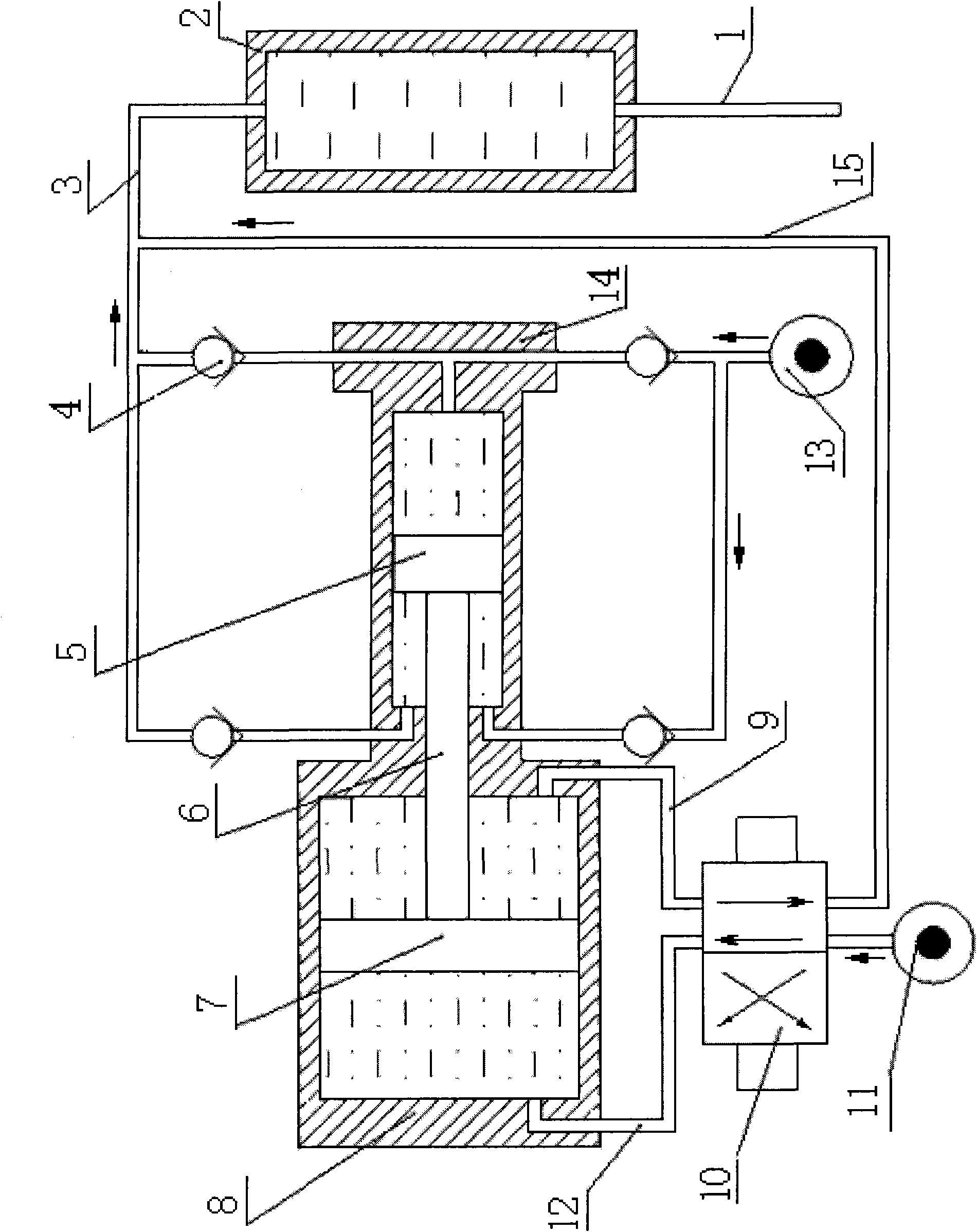
[0032] refer to figure 1 . The differential pressure power booster is mainly composed of a compression cylinder discharge pipe 3, a one-way valve 4, a small piston 5, a piston rod 6, a large piston 7, a drive cylinder 8, a high-pressure right inlet and exhaust pipe 9, and a two-position four-way reversing Valve 10, high-pressure left intake and exhaust pipe 12, compression cylinder 14 and drive cylinder gas discharge pipe 15 form.

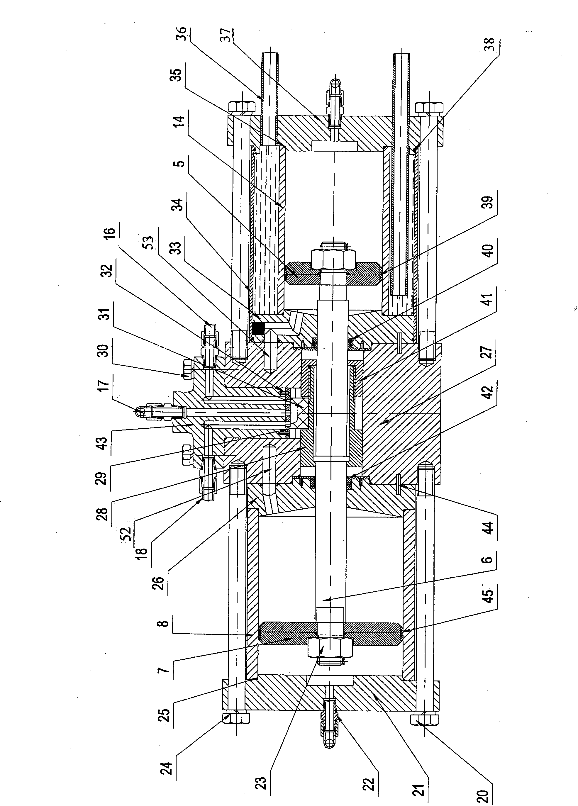
[0033] The driving cylinder 8 and the compression cylinder 14 are relatively connected together, the centerline of the driving cylinder 8 and the centerline of the compression cylinder 14 are the same straight line, and there is a piston rod 6 between the driving cylinder 8 and the compression cylinder 14. Both ends are respectively fixed with a large piston 7 and a small piston 5, the large piston 7 is in ...

Embodiment 2

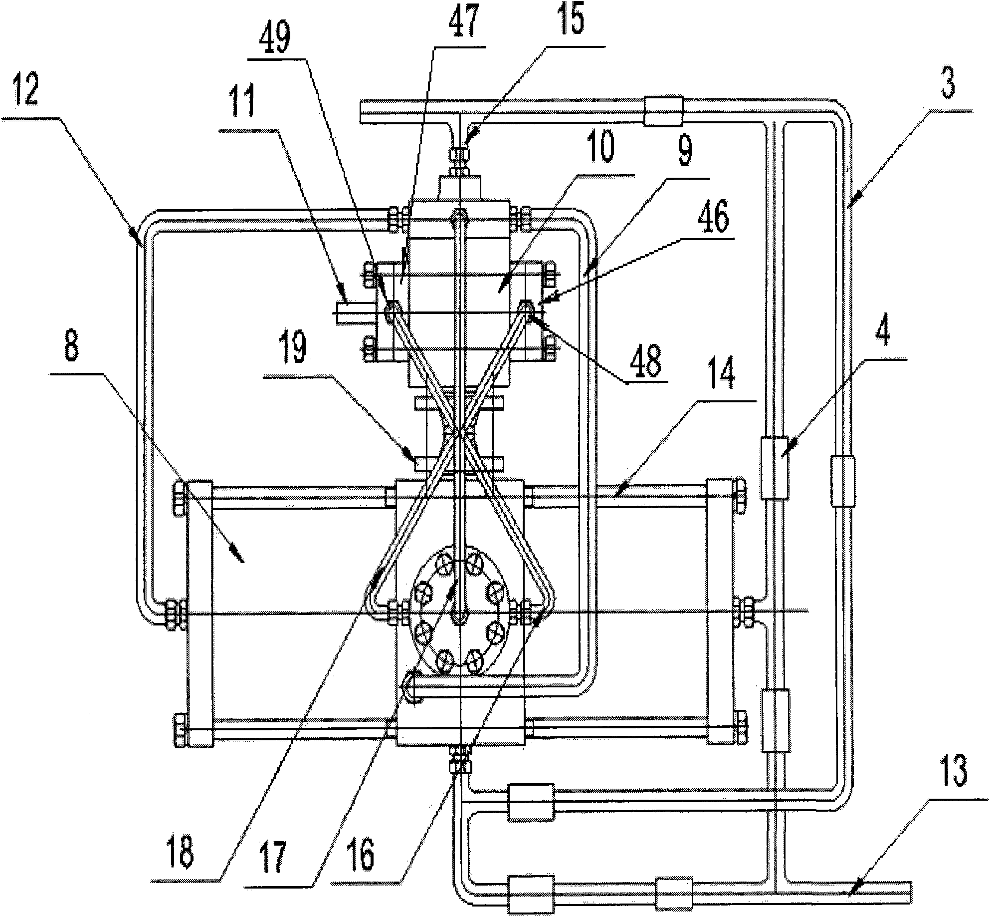
[0044] Embodiment 2: see Figure 4 . Embodiment 2 is basically the same as Embodiment 1, the difference is: the two-position four-way reversing valve 10 is replaced with a two-position four-way solenoid valve 51, which is on the outer edge of the drive cylinder left cover 21 and the drive cylinder right A magnetic progressive switch 50 is respectively fixed on the outer edge of the cover 26. The magnetic progressive switch 50 is respectively connected to the two-position four-way solenoid valve 51, and the electric signal fed back by the magnetic progressive switch 50 controls the two-position four-way solenoid valve 51 to change direction. .


PUM


Abstract

The invention relates to a differential pressure power pressure booster, which is applied to the technical field of natural gas exploitation. The pressure of a high-pressure gas well is used for increasing the pressure of a low-pressure gas wall. A driving cylinder is oppositely connected with a compressing cylinder; a piston rod is arranged between the driving cylinder and the compressing cylinder; the left cavity of the driving cylinder is communicated with a high-pressure left gas inlet and outlet pipe, and the right cavity of the driving cylinder is communicated with a high-pressure right gas inlet and outlet pipe; the high-pressure left gas inlet and outlet pipe and the high-pressure right gas inlet and outlet pipe are connected with a two-position four-way change valve respectively; the two-position four-way change valve is connected with a high-pressure gas inlet pipe; the left cavity and the right cavity of the compressing cylinder are provided with a low-pressure gas inlet and a compressed low pressure gas outlet respectively; and a low-pressure gas inlet pipeline is fixed with a check valve, is connected with a low-pressure gas inlet pipe through the check valve, and is connected with an outlet pipe of the compressing cylinder through the check valve. The differential pressure power pressure booster has the advantages of exploiting natural gas of the low-pressure gas wall by using natural gas of the high-pressure gas well as a driving force under the condition of no external power source, saving a great amount of production cost, and effectively protecting strata pressures.

Description

technical field [0001] The invention relates to the technical field of natural gas exploitation, in particular to a natural gas booster device for increasing the pressure of a low-pressure gas well by using the pressure of a high-pressure gas well, and is a natural gas booster for exploiting a low-pressure gas well. Background technique [0002] With the large-scale development and utilization of natural gas resources, many natural gas fields have entered the mid-to-late stage of development, the storage of natural gas in the formations has decreased, the pressure of natural gas in the formations has decreased, and the pressure of gas wells has gradually decreased. It will increase year by year, and when the pressure of many gas wells cannot meet the pressure requirements of pipeline transportation, it is necessary to increase the outlet pressure of formation natural gas to meet pipeline transportation. Chinese Patent Publication No.: CN201106440 discloses a "Single Well Pre...

Claims


Application Information

Patent Timeline
Patent Type & Authority Applications(China)
IPC IPC(8): F04B39/00E21B43/18
Inventor 宗贻平李丙文龙金明解建辉谢光辉李国勋袁联营
Owner PETROCHINA CO LTD
Why Eureka
Try Eureka