Valve core of ball valve and processing method thereof

A valve core and ball valve technology, which is applied in the field of ball valve cores, can solve the problems of high consumption of raw materials, low structural strength, and large weight of components, etc., and achieve the effects of less raw material consumption, low manufacturing cost, and small weight.

Inactive Publication Date: 2011-04-27
张晓丰
View PDF5 Cites 6 Cited by
  • Summary
  • Abstract
  • Description
  • Claims
  • Application Information

AI Technical Summary

Problems solved by technology

The traditional ball valve spool mainly has two structures, one is a solid ball structure, and a through hole is opened on the sphere of the solid sphere for the liquid to flow through. The spool of this structure has higher strength, The pressure resistance performance is good, but the weight of the parts is heavy, the raw material consumption is large, and the manufacturing cost is high; the other is a hollow ball structure, and the liquid inlet and outlet connected to the inner hole are arranged on the ball. The position of the liquid port is facing; in order to facilitate the installation of the valve stem, there is a groove on the outer surface of the ball
Although the spool of this hollow ball structure overcomes the defects of solid balls and has the advantages of small weight, low raw material consumption, and low manufacturing cost, it has low structural strength and poor pressure resistance. Need to solve the above technical problems

Method used


Image

  • Valve core of ball valve and processing method thereof
  • Valve core of ball valve and processing method thereof
  • Valve core of ball valve and processing method thereof

Examples


Embodiment Construction

[0021] Below in conjunction with accompanying drawing and embodiment the present invention will be further described:

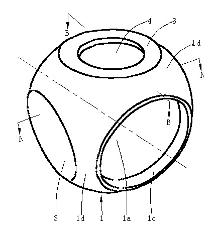
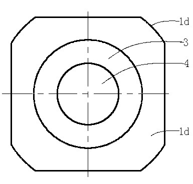
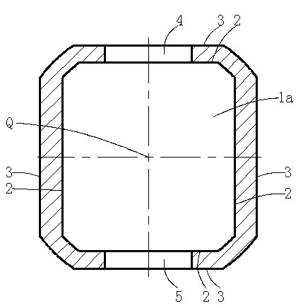
[0022] Such as Figure 1~4 As shown, a ball valve spool includes a sphere 1, the sphere 1 is a hollow structure, and the sphere 1 is provided with a liquid inlet 1b and a liquid outlet 1c communicating with the inner hole 1a, and the liquid inlet 1b and the liquid outlet The position of mouth 1c is opposite, and the size is the same. The structures of the sphere 1 and the liquid inlet and outlet are prior art, and will not be repeated here. During use, the liquid flows into the valve core through the liquid inlet 1b, passes through the inner hole 1a, and then flows out of the valve core through the liquid outlet 1c.

[0023] The outer surface of the sphere 1 is an arc surface 1d, and the structure of the arc surface 1d is in the prior art, and will not be repeated here. In order to strengthen the structural strength of the spool, four inner planes 2 parall...


PUM

PropertyMeasurementUnit
diameteraaaaaaaaaa

Abstract

The invention discloses a valve core of a ball valve. The valve core of the ball valve comprises a ball body, wherein the ball body has a hollow structure; a liquid inlet and a liquid outlet which are communicated with an inner hole is arranged on the ball body; and the liquid inlet is opposite to the liquid outlet. The key point is that: four planes parallel to the central line of the inner hole are formed on the inner surface and the outer surface of the ball body respectively; four inner planes and four outer planes of the ball body are in one-to-one correspondence; each outer plane is distributed uniformly along the circumferential direction of the ball body; the two adjacent outer planes are vertical to each other; the two opposite outer planes are over against each other; a first valve rod mounting through hole is formed on any one of the outer planes; a second valve rod mounting through hole is formed on the outer plane opposite to the former outer plane; and the central line of the second valve rod mounting through hole coincides with the central line of the first valve rod mounting through hole and is vertical to the central line of the inner hole. The valve core of the ball valve integrates the advantages of the valve core of the traditional solid ball structure and the valve core of the traditional hollow ball structure, has the advantages of light weight, low consumption of raw materials, low manufacturing cost, high structural strength and high pressure resistance, and is suitable for large-scale popularization and application.

Description

technical field [0001] The invention belongs to a ball valve component, in particular to a ball valve core. Background technique [0002] The spool is an important part of the ball valve. It is installed in the valve body to control the flow of the liquid. We generally distinguish various ball valve spools by pressure rating. The pressure rating of the commonly used spool is 16kg to 320kg. The traditional ball valve spool mainly has two structures, one is a solid ball structure, and a through hole is opened on the sphere of the solid sphere for the liquid to flow through. The spool of this structure has higher strength, The pressure resistance performance is good, but the weight of the parts is heavy, the raw material consumption is large, and the manufacturing cost is high; the other is a hollow ball structure, and the liquid inlet and outlet connected to the inner hole are arranged on the ball. The position of the liquid port is facing; in order to facilitate the installa...

Claims


Application Information

Patent Timeline
Patent Type & Authority Applications(China)
IPC IPC(8): F16K5/08F16K5/06B23P15/00
Inventor 张轩
Owner 张晓丰
Why Eureka
Try Eureka