Elevator power supply device

A technology for power supply devices and elevators, which is applied in the directions of circuit devices, electrical components, transportation and packaging, etc. It can solve the problems of reducing the safety of elevators, high production costs, and increasing the complexity of elevator manufacturing. The realization method is simple and easy to use, The effect of improving the safe operation factor

Inactive Publication Date: 2011-05-04
HARMOTECH TECH BEIJING +1
View PDF6 Cites 13 Cited by
  • Summary
  • Abstract
  • Description
  • Claims
  • Application Information

AI Technical Summary

Problems solved by technology

[0006] 1. Since the elevator emergency device must have necessary parts such as control loops, leveling sensors, brake coils, etc., to take over the elevator control system to control the operation of the car when the mains power is interrupted, its circuit structure is usually relatively complicated. higher production costs
And because most elevator manufacturers need to order elevator emergency devices from specialized elevator emergency device manufacturers, the high cost of elevator emergency devices will bring a burden to the elevator manufacturing industry when the sales profit of the elevator itself is not high.
[0007] 2. Since the elevator emergency device needs to completely take over the elevator's own control system when the mains power is interrupted, some corresponding changes need to be made to the internal circuit structure of the elevator's own control system to cooperate with the control operation of the elevator emergency device, which not only increases It increases the complexity of elevator manufacturing, further increases the manufacturing cost, and the complete takeover of the elevator control system will reduce the safety of the elevator itself

Method used


Image

  • Elevator power supply device
  • Elevator power supply device
  • Elevator power supply device

Examples


Embodiment Construction

[0030] Embodiments of the present invention will be described in detail below with reference to the drawings.

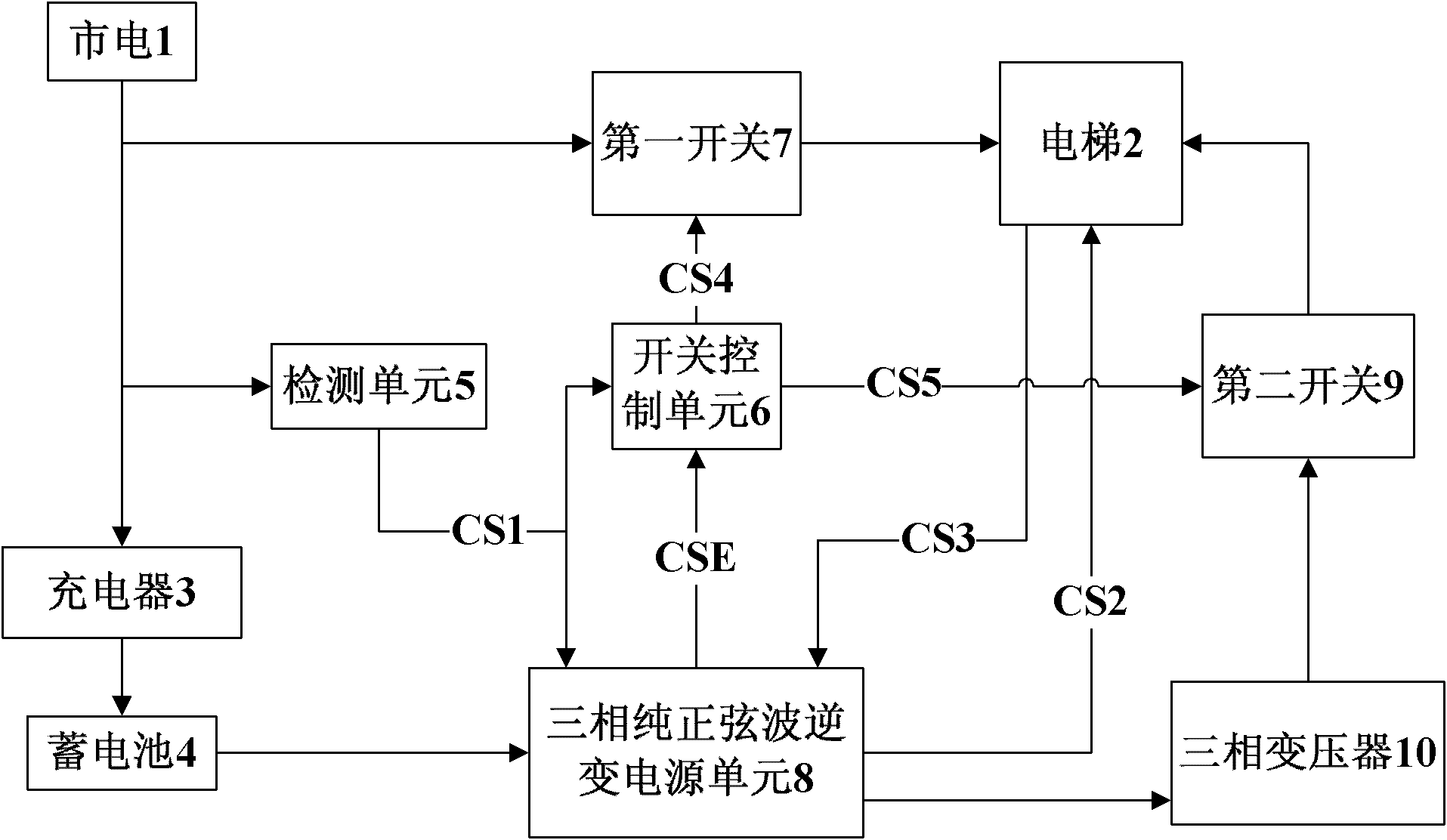
[0031] figure 2 It is a structural schematic diagram of the elevator power supply device of the present invention, such as figure 2 As shown, the elevator power supply device of the present invention includes a first switch 7, a second switch 9, a detection unit 5, a switch control unit 6, a three-phase pure sine wave inverter power supply unit 8, a three-phase transformer 10, a charger 3 and a storage battery 4.

[0032] Wherein, the first switch 7 is connected between the commercial power 1 and the elevator 2 to transmit the commercial power to the elevator 2, and the detection unit 5 is connected to the commercial power 1 to detect whether the commercial power is interrupted. The charger 3 is connected to the commercial power 1 and the storage battery 4 to charge the storage battery 4 with the commercial power. The battery 4 is connected to the three-phase pu...


PUM


Abstract

The invention relates to an elevator power supply device which comprises a charger, a battery, a detecting unit, a three-phase pure sine wave inverter power unit, a first switch, a second switch, a switch control unit and a three-phase transformer, wherein the battery is connected with the charger, the detecting unit is connected to mains supply, and the three-phase pure sine wave inverter power unit is connected to the battery and the detecting unit and is used to start emergency operation to output three-phase pure sine wave PWM signals when the mains supply is disconnected; the first switch is connected between the mains supply and the elevator; the second switch is connected between the elevator and the three-phase transformer; the switch control unit is connected to the detecting unit, the first switch and the second switch and has a control part to control the first switch and the second switch; and the three-phase pure sine wave inverter power unit is connected between the three-phase transformer and the second switch. The elevator power supply device can ensure that an elevator can operate normally for certain time after the mains supply is disconnected without changing the elevator control system. With the advantage of simplicity, the elevator power supply device can improve the overall safety factor of the elevator.

Description

technical field [0001] The invention relates to a power supply device, in particular to an elevator power supply device with an emergency function. Background technique [0002] In the elevator equipment, when the mains power supply is interrupted suddenly, the operation of the elevator car can be controlled by manually or automatically starting the emergency device. [0003] An elevator emergency device usually includes a control unit, a battery, a charging unit, a single-phase or three-phase inverter unit, a drive unit, a relay, a static switch, an operation panel, etc. The control unit is connected to the battery, the brake coil, and the elevator door operator. After a power failure, the control unit in the elevator emergency device controls the brake coil and the elevator door machine to level the elevator car and open the door. [0004] figure 1 It is a structural diagram of an existing elevator emergency device. Such as figure 1 As shown, the elevator emergency dev...

Claims


Application Information

Patent Timeline
Patent Type & Authority Applications(China)
IPC IPC(8): B66B5/02H02J9/06
Inventor 张长安
Owner HARMOTECH TECH BEIJING
Why Eureka
Try Eureka