Method for coproducing substitute natural gas through coal liquefaction

A technology for substituting natural gas and coal-to-oil, which is applied in the petroleum industry, the preparation of gaseous fuels, liquid hydrocarbon mixtures, etc., can solve the problems of no combined process of coal-to-oil and coal-to-natural gas, and achieve the goal of reducing investment and operating costs Effect

Active Publication Date: 2011-05-04
CHINA PETROLEUM & CHEM CORP +1
View PDF2 Cites 11 Cited by
  • Summary
  • Abstract
  • Description
  • Claims
  • Application Information

AI Technical Summary

Problems solved by technology

[0006] There is no combined process of coal-to-oil and coal-to-natural gas in the prior art

Method used


Image

  • Method for coproducing substitute natural gas through coal liquefaction
  • Method for coproducing substitute natural gas through coal liquefaction
  • Method for coproducing substitute natural gas through coal liquefaction

Examples


Embodiment 1

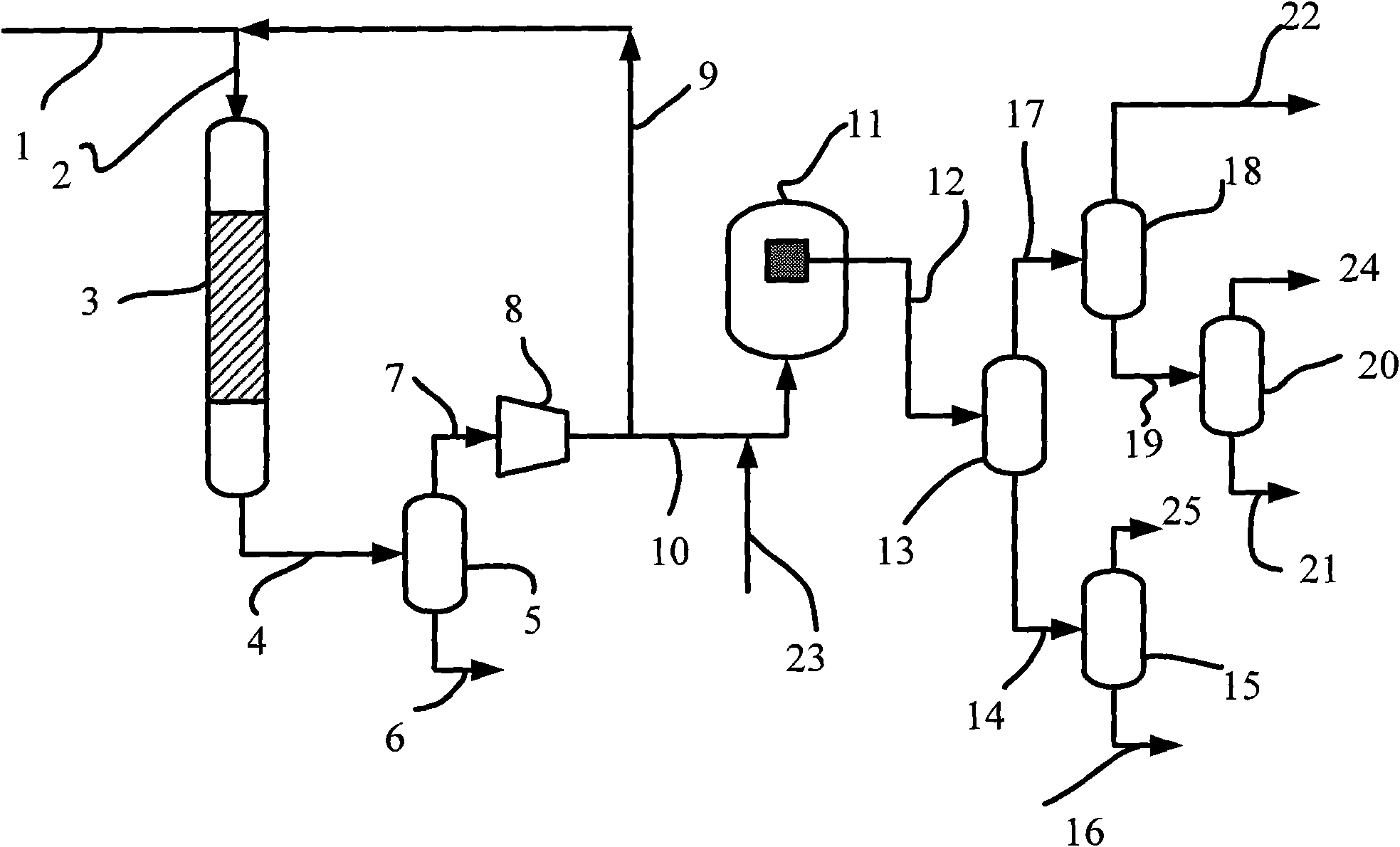
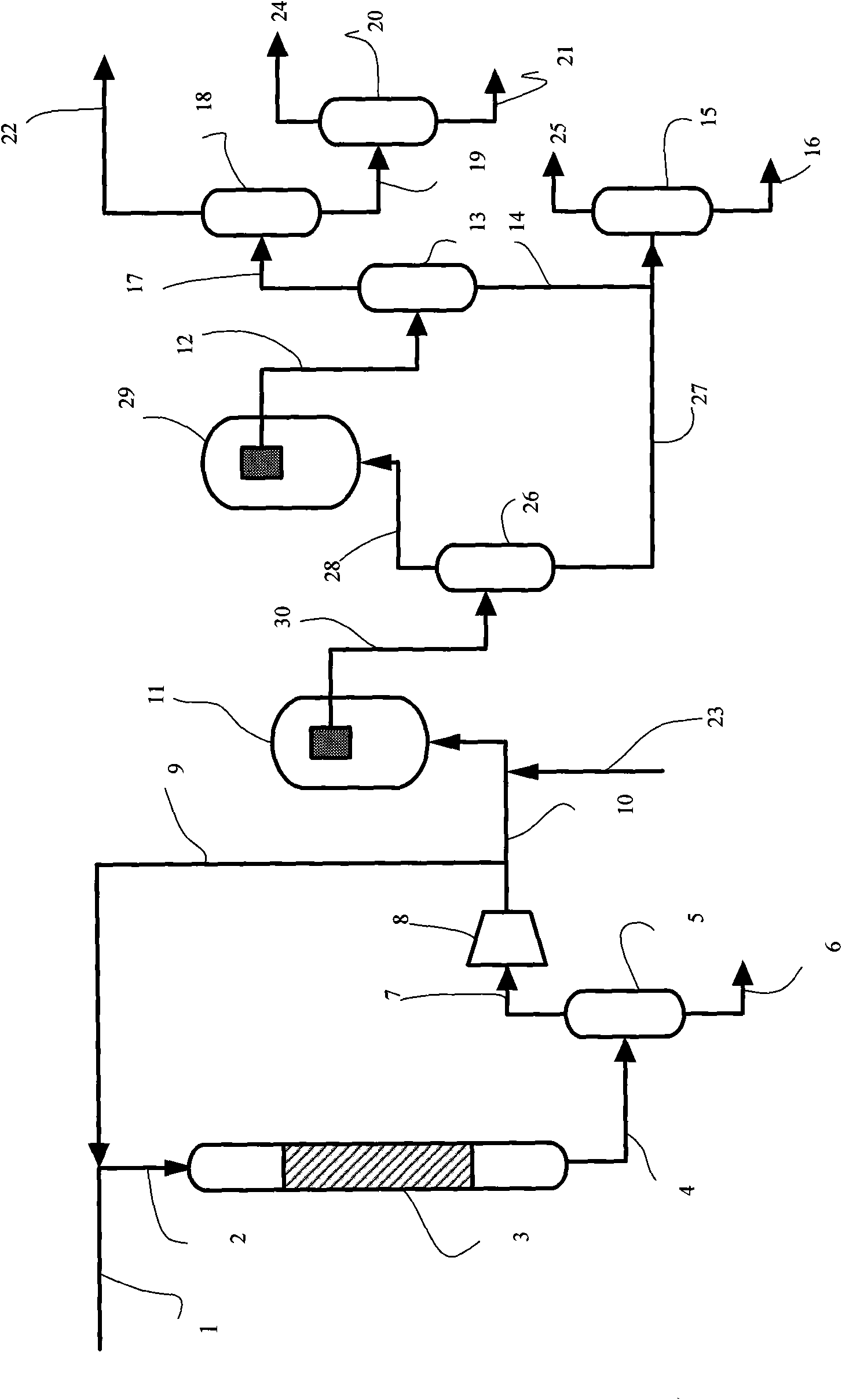
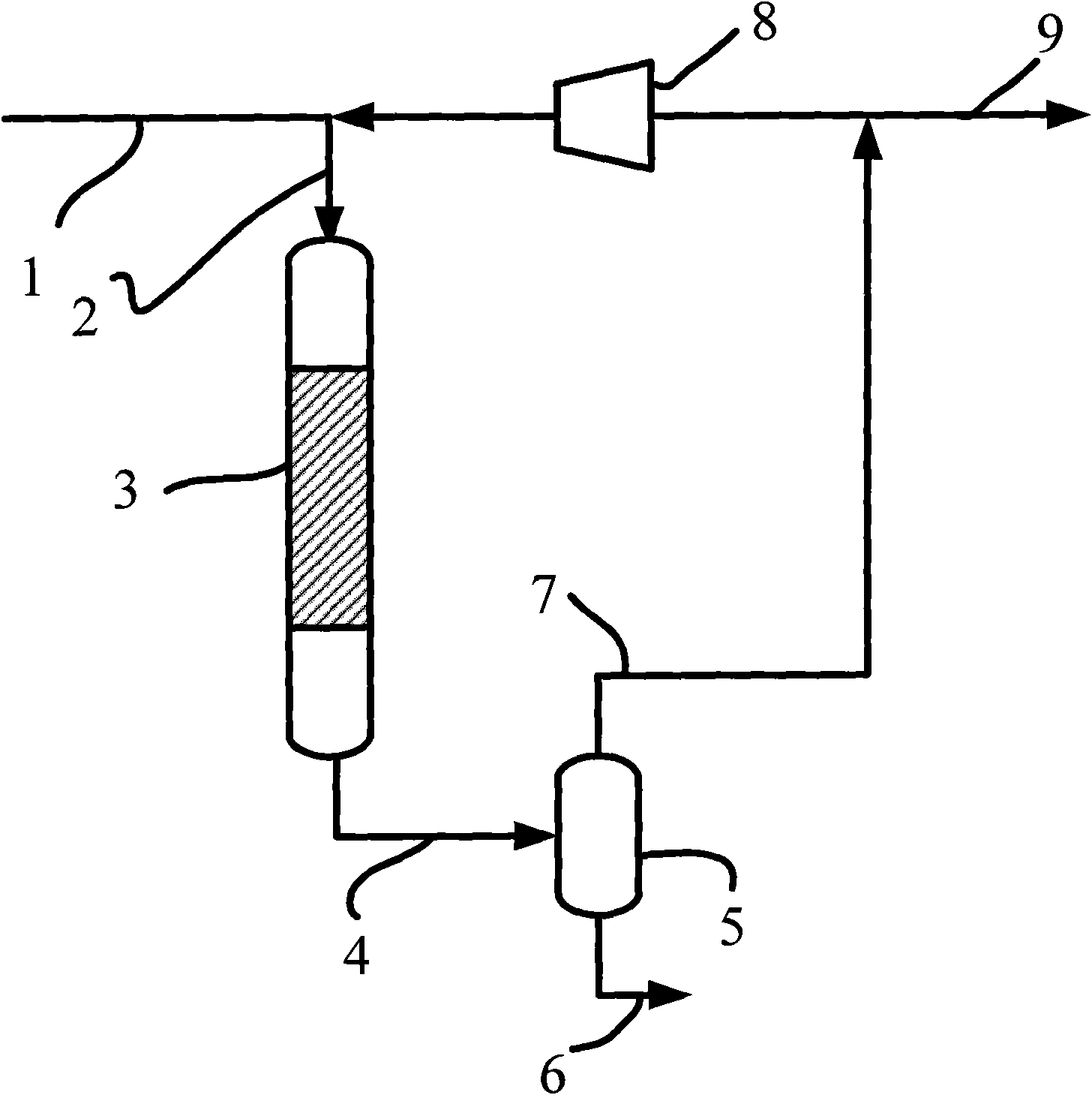
[0037] This embodiment adopts figure 1 The process flow shown.

[0038] The specific process is as follows: coal is gasified to obtain 2 The synthesis gas including CO, the synthesis gas enters the methanation reactor 3 through the pipeline 1 and the pipeline 2, and reacts under the action of the methanation catalyst, and the reaction effluent enters the high-pressure separator 5 through the pipeline 4 for gas-liquid separation, The resulting condensed liquid flow, i.e. liquid I, is discharged from the system through line 6, and the resulting gas flow, i.e. gas I, enters compressor 8 through line 7, and after being pressurized by the compressor, part of gas I is recycled back to methanation reactor 3 through line 9 Participate in reactions further. The gas I not recycled back to the methanation reactor 3 enters the Fischer-Tropsch synthesis reactor 11 through the pipeline 10, and undergoes a Fischer-Tropsch synthesis reaction under the action of the Fischer-Tropsch synthesis...

Embodiment 2

[0048] This embodiment adopts figure 2 The process flow shown.

[0049] The specific process is as follows: coal is gasified to obtain 2 The synthesis gas including CO, the synthesis gas enters the methanation reactor 3 through the pipeline 1 and the pipeline 2, and reacts under the action of the methanation catalyst, and the reaction effluent enters the high-pressure separator 5 through the pipeline 4 for gas-liquid separation, The resulting condensed liquid flow, i.e. liquid I, is discharged from the system through line 6, and the resulting gas flow, i.e. gas I, enters compressor 8 through line 7, and after being pressurized by the compressor, part of gas I is recycled back to methanation reactor 3 through line 9 Participate in reactions further. The gas I that is not recycled back to the methanation reactor 3 enters the first Fischer-Tropsch synthesis reactor 11 through the pipeline 10, and carries out the Fischer-Tropsch synthesis reaction under the action of the Fische...


PUM


Abstract

The invention relates to a method for coproducing substitute natural gas through coal liquefaction. Synthetic gas obtained by gasifying coal enters a methanation reactor, water generated in the methanation process is separated out of a material flow at the outlet of the methanation reactor through gas-liquid separation, the gas is partially circulated back to the inlet of the methanation reactor to further participate in the reaction, and the uncirculated gas enters a Fischer-Tropsch synthesis reactor. Synthetic oil and gas are obtained through the cooling and the gas-liquid separation of thematerial flow at the outlet of the methanation reactor, the CH4 in the gas is further separated out, and the gas rich in the CH4 is used as the substitute natural gas to be output. The synthetic oil and the substitute natural gas are simultaneously produced by the coal, and thereby the invention not only solves the problem of difficult control for the temperature of the Fischer-Tropsch synthesis reactor, but also saves a circulating compressor of a Fischer-Tropsch synthesis device. The product distribution of Fischer-Tropsch synthesis is not changed while the substitute natural gas is coproduced, and the high-proportion heavy hydrocarbon can also be obtained through the Fischer-Tropsch synthesis.

Description

technical field [0001] The invention relates to a method for converting coal into gaseous hydrocarbons and liquid hydrocarbons, more specifically, a combined method of synthesis gas methanation and Fischer-Tropsch synthesis. Background technique [0002] my country's energy structure is "coal-rich, oil-deficient, and gas-poor". This feature determines that seeking alternative energy sources from oil and gas is a long-term strategy for my country's economic development and energy strategic security. my country's rich coal resources provide a broad market for the development of the coal chemical industry. [0003] The high oil price and the instability of oil supply have given birth to the rapid development of alternative energy sources, and the energy issue has become the focus of attention all over the world. In this context, starting from the strategic height of national energy security, the development of alternative energy suitable for my country's national conditions ha...

Claims


Application Information

Patent Timeline
Patent Type & Authority Applications(China)
IPC IPC(8): C10G2/00C10L3/08
Inventor 吴昊胡志海聂红李猛徐润侯朝鹏夏国富
Owner CHINA PETROLEUM & CHEM CORP
Why Eureka
Try Eureka