
Method for water control and oil production increasing acidification of oil well at water content increasing stage of low-pressure heterogeneous reservoir

A heterogeneous reservoir and stage technology, applied in the direction of earthwork drilling, wellbore/well components, production fluid, etc., can solve the problems of small oil increase effect, no oil increase, and water production increase in oil wells

Active Publication Date: 2011-05-04
PETROCHINA CO LTD
View PDF8 Cites 7 Cited by
  • Summary
  • Abstract
  • Description
  • Claims
  • Application Information

AI Technical Summary

Problems solved by technology

[0002] The production of oil wells in low-pressure heterogeneous reservoirs is greatly reduced due to the increase of water cut; due to the low pressure of the reservoir, if conventional acidizing is adopted, the acidizing treatment liquid will first flow along the fractures or large pores of the water outlet under the pressure of the wellbore fluid column and will seep into the deep part of the formation, or even deeper into the oil-water interface, so that the acid cannot enter the clogged oil seepage channels, resulting in a very small increase in oil well and a greater increase in water production; in most cases, acidizing Afterwards, no oil is produced, and a large amount of water is produced, which makes the oil well almost scrapped; if the water plugging (temporary plugging) is used first and then acidizing, the plugging agent cannot be injected due to the serious blockage of the oil layer, and the pressure rise will cause fractures, and the acidizing result will not only increase Oil, but lead to a significant increase in water production

Method used


Image

  • Method for water control and oil production increasing acidification of oil well at water content increasing stage of low-pressure heterogeneous reservoir
  • Method for water control and oil production increasing acidification of oil well at water content increasing stage of low-pressure heterogeneous reservoir

Examples


Embodiment Construction

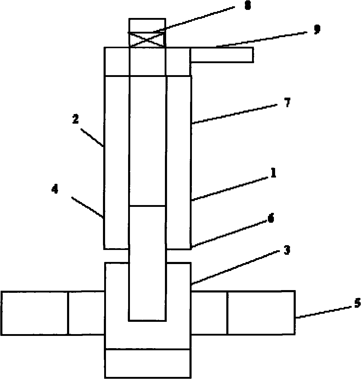
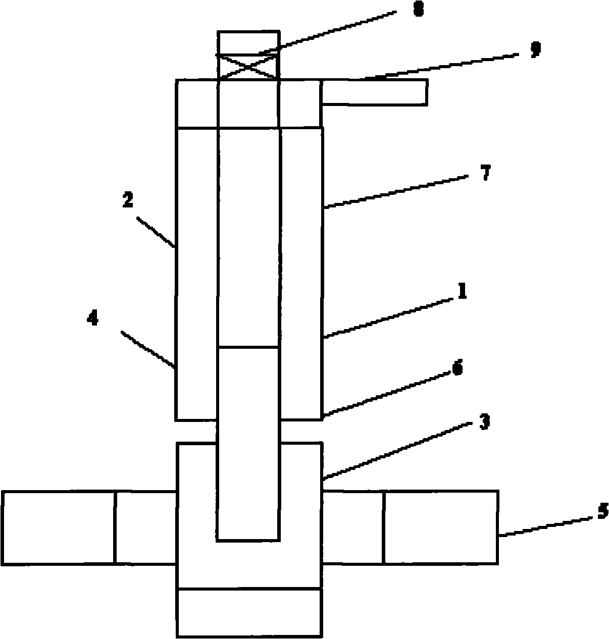
[0009] Firstly, wash the wellbore circularly with well flushing fluid (0.5% clay stabilizer + 0.3% 8608 active agent) 1 and fill the casing 2; , acetic acid 6-10%, corrosion inhibitor 0.5%-1%, iron ion stabilizer 1%-2%, surfactant 0.3-0.5%) 3 replace the flushing fluid in the oil pipe 4 to the middle part of the oil layer 5; sit well Packer 6, use high-viscosity displacement fluid (xanthan gum heated to 90°C to dissolve at 0.5%) 7 to displace the acidizing fluid in the tubing into the oil layer, respectively close the tubing gate 8 and casing gate 9 to react for a certain period of time, Suction the flowback with a tubing aspirator.


PUM


Abstract

The invention relates to a method for the water control and oil production increasing acidification of an oil well at the water content increasing stage of a low-pressure heterogeneous reservoir, which comprises the following steps of: washing a shaft by using a flushing fluid, and filling the flushing fluid into a sleeve; replacing the flushing fluid in an oil tube with acidification liquid, and introducing the acidification liquid into the middle part of an oil layer; sealing well a packer seat, sealing an annular space of an oil jacket, replacing the acidification liquid in the oil tube with high-viscosity displacing liquid, introducing the displacing liquid into the oil layer, fastening an oil tube valve and a sleeve valve up, performing reaction for 30min to 8h, and performing pumping and flow back by using an oil tube swab; when an acid flooding pressure is less than or equal to 7MPa, replacing the acidification liquid with the high-viscosity displacing liquid in a volume which is 2 / 3 of that of the oil tube of the shaft, and performing reaction for 3h; when the acid flooding pressure is more than or equal to 7MPa, replacing the acidification liquid with the high-viscosity displacing liquid in the volume which is 4 / 5 of that of the oil tube of the shaft, and performing reaction for 3h; and after the pressure is released, opening the mouth of the well, and setting an oil tube pumping drum for pumping and flow back until reaching a water oil ratio, wherein the deepest pumping position is 300 to 500m above a perforated interval of the oil layer. The method avoids the probability of high water yield of the acidified oil well, poor effects achieved by measures or scrap of the oil well.

Description

Technical field: [0001] The invention relates to an acidizing method suitable for controlling water and increasing oil in oil wells of low-pressure heterogeneous oil reservoirs. Background technique: [0002] The production of oil wells in low-pressure heterogeneous reservoirs is greatly reduced due to the increase of water cut; due to the low pressure of the reservoir, if conventional acidizing is adopted, the acidizing treatment liquid will first flow along the fractures or large pores of the water outlet under the pressure of the wellbore fluid column and will seep into the deep part of the formation, or even deeper into the oil-water interface, so that the acid cannot enter the clogged oil seepage channels, resulting in a very small increase in oil well and a greater increase in water production; in most cases, acidizing Afterwards, no oil is produced, and a large amount of water is produced, which makes the oil well almost scrapped; if the water plugging (temporary plug...

Claims


Application Information

Patent Timeline
Patent Type & Authority Applications(China)
IPC IPC(8): E21B43/27
Inventor 黎晓茸杨华徐永高张书平赵振峰杨承宗李永长杨立华张涛马丽萍
Owner PETROCHINA CO LTD
Learn More