Damper and door handle having the same

A technology for dampers and door handles, applied in the field of dampers and door handles, can solve the problem of torque reduction and achieve the effect of torque reduction

Inactive Publication Date: 2005-08-03
NIFCO INC +1
View PDF3 Cites 11 Cited by
  • Summary
  • Abstract
  • Description
  • Claims
  • Application Information

AI Technical Summary

Problems solved by technology

[0018] However, in Patent Document 3, since the rotating member 150 and the valve body 154 always rotate in an integrated state, even if the gap formed by the upper surface of the convex portion and the groove 168 forms a bypass channel for the v

Method used


Image

  • Damper and door handle having the same
  • Damper and door handle having the same
  • Damper and door handle having the same

Examples


Example Embodiment

[0066] Next, a damper according to an embodiment of the present invention will be described.
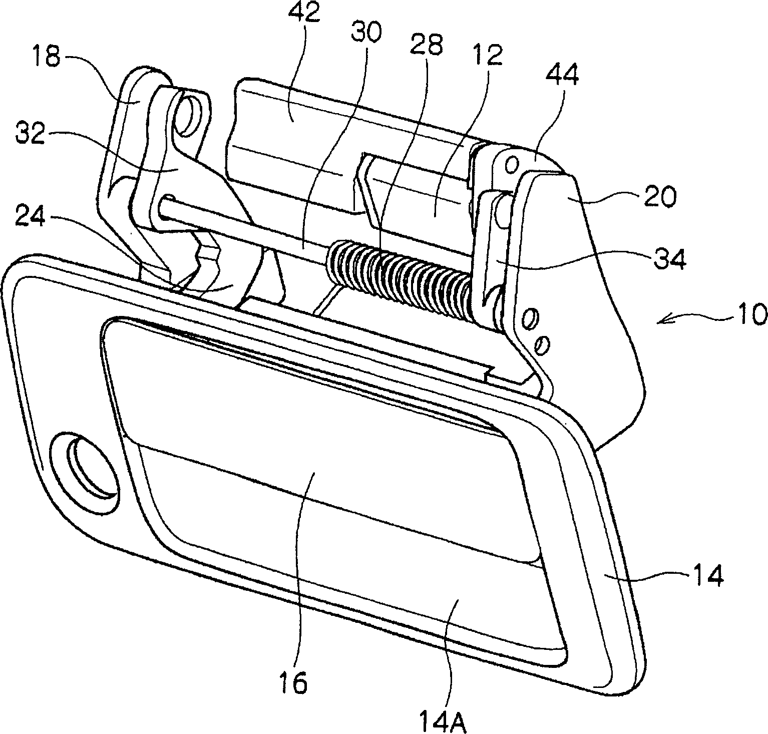
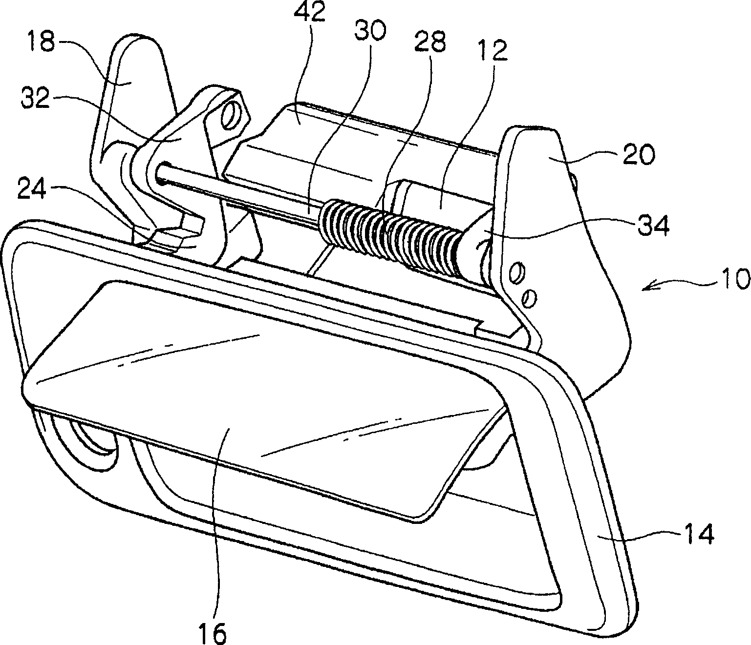
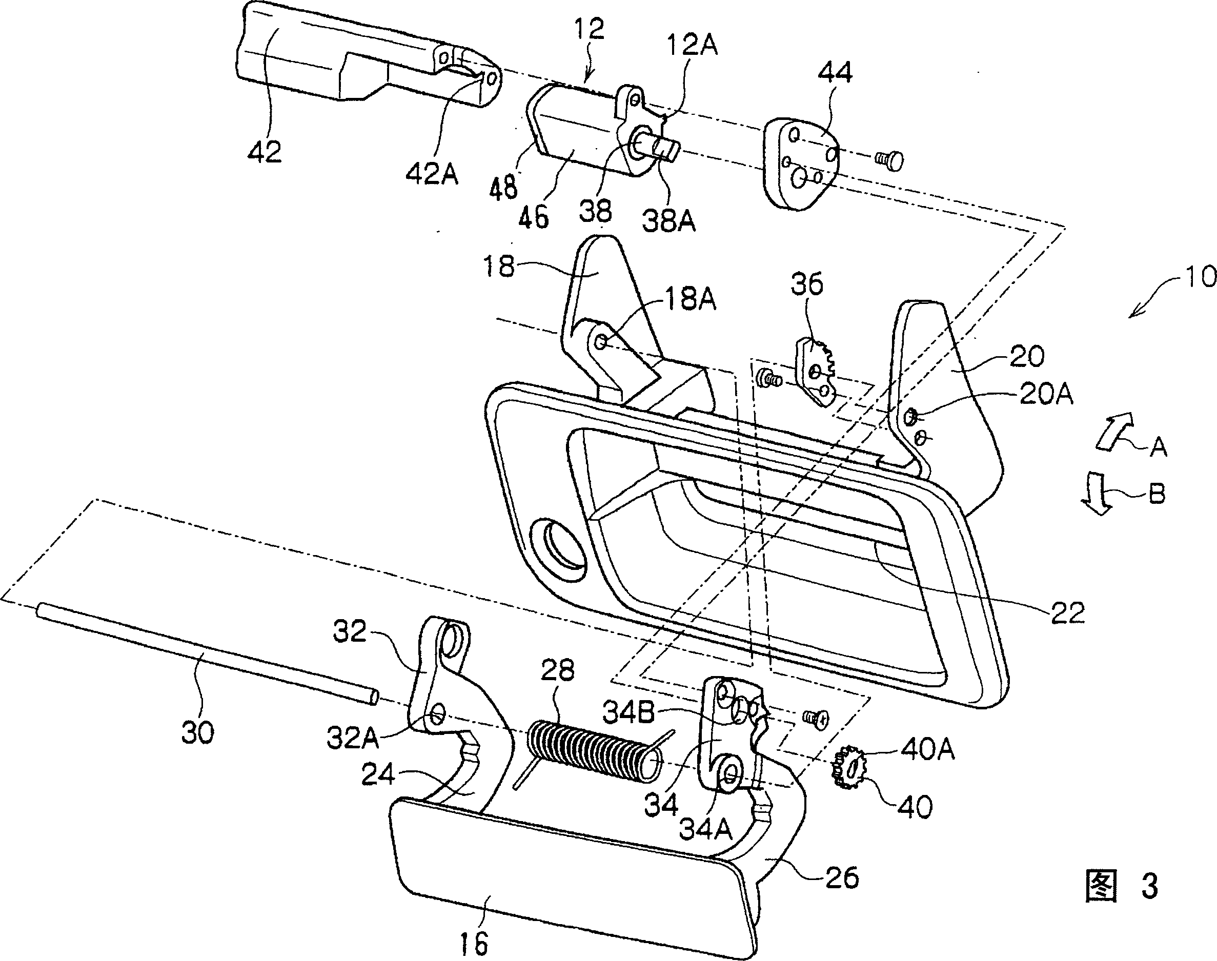
[0067] like figure 1 As shown in FIG. 3 , a door (not shown) of an automobile is provided with a door handle 10 for opening and closing the door, and the damper 12 of the present embodiment is used for this door handle 10 .

[0068] The door handle 10 can be roughly divided into two parts: a main body part 14 and an operating handle 16 .

[0069] A pair of fixing plates 18, 20 protrude from the inner surface of the main body portion 14 and are fixed to a panel (not shown) of the vehicle. In addition, on the surface of the main body portion 14, a recessed portion 14A capable of accommodating the operating handle 16 is provided, an opening portion 22 is formed in the recessed portion 14A, and a pair of cantilevers protruding from the inner surface of the operating handle 16 is provided. 24, 26 can pass through this opening portion.

[0070] Axle hole portions 18A, 20A are formed on...


PUM


Abstract

A damper 12 for a door handle comprises a rotor 50 and a valve 56 which are completely separated and only the rotor 50 rotates, so that it is possible to significantly reduce the torque applied to the rotor 50. When the rotor 50 and the valve 56 are connected, or separated , torque applied to the rotor 50 is changed greatly. Accordingly, instead of gradually changing torque according to a rotational angle of the rotor 50, it is possible to set a specific point where torque is changed.

Description

technical field [0001] The present invention relates to a damper and a door handle with such a damper. Background technique [0002] Such as Figure 12 As shown, in the damper for high torque disclosed in U.S. Patent No. 5,743,575 (Patent Document 1), a through hole 100A is formed on a backing plate 100 of an automobile door panel, and a pair of On the inner surface of the operating handle 102, a pivotally supported lever 106 passes through the through hole 100A to work as a crank member. [0003] Further, on the inner surface of the backing plate 100, a pair of raised raised portions 104 are provided, and a pivotally supported lever 106 is arranged inside the raised portions 104 in a state adjacent to the raised portions 104. As shown in FIG. Further, a bearing portion 112 formed with a shaft hole 110 having a square cross section is rotatably attached to the boss portion 104 . [0004] Wherein, the square rotating shaft 114A protrudes from both ends of the cylindrical da...

Claims


Application Information

Patent Timeline
IPC IPC(8): E05B1/00A45C3/00B60J5/04E05B17/00E05B77/42E05B83/30E05B85/18F16F9/14
CPCY10T16/464F16F9/145Y10T16/458E05B85/18Y10T16/2771E05B17/0041E05B77/42A47G1/08A47G2200/16
Inventor 林见
Owner NIFCO INC
Why Eureka
Try Eureka