
Side-to-side thermal deashing method for rotary air preheater

A technology of air preheater and rotary type, which is applied in the direction of combustion method, solid residue removal, lighting and heating equipment, etc. It can solve the problems of improving the denitrification rotary air preheater and reducing the design efficiency of power plant boilers, etc., and achieves the improvement Design efficiency, reduce fan power consumption, and avoid abnormal rise

Active Publication Date: 2012-08-29
章礼道
View PDF2 Cites 2 Cited by
  • Summary
  • Abstract
  • Description
  • Claims
  • Application Information

AI Technical Summary

Problems solved by technology

The oxidation characteristics of the SCR catalyst can convert a small amount of SO in the flue gas 2 Oxidation to SO 3 , SO 3 It can react with escaped ammonia to form ammonium bisulfate. The dew point of ammonium bisulfate is as high as 176°C. It cannot be blown through with a soot blower. The conventional denitrification rotary air preheater of a utility boiler adopts an increase in the height of the heat transfer element in the low temperature section and cancels the heat transfer element in the middle temperature section; the heat transfer element uses a small closed flow channel to ensure that the blowing air flow passes The use of enamel surface heat transfer elements; the use of duplex (steam and high-pressure water) soot blowing system; technical means such as increasing the exhaust gas temperature under the design load of power plant boilers, the adoption of these technical means has greatly improved Reduced the cost of the denitrification rotary air preheater, and also reduced the design efficiency of the power plant boiler

Method used


Image

  • Side-to-side thermal deashing method for rotary air preheater
  • Side-to-side thermal deashing method for rotary air preheater
  • Side-to-side thermal deashing method for rotary air preheater

Examples


Embodiment Construction

[0039] The preparatory conditions for the implementation of side-by-side hot ash cleaning of the rotary air preheater should meet the following requirements:

[0040] a. The boiler load of the power station is lower than 60% of the rated load but higher than the minimum load of the boiler without fuel injection and stable combustion;

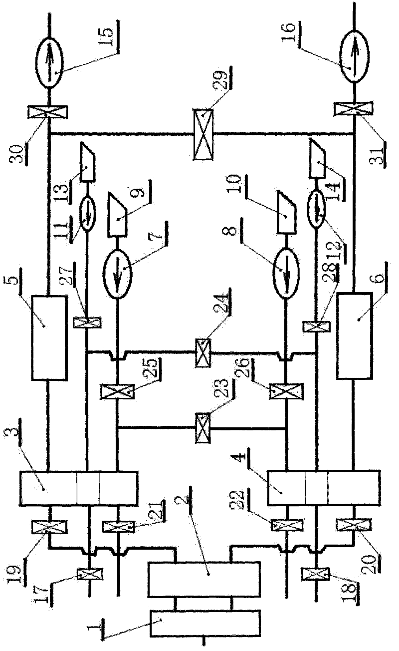
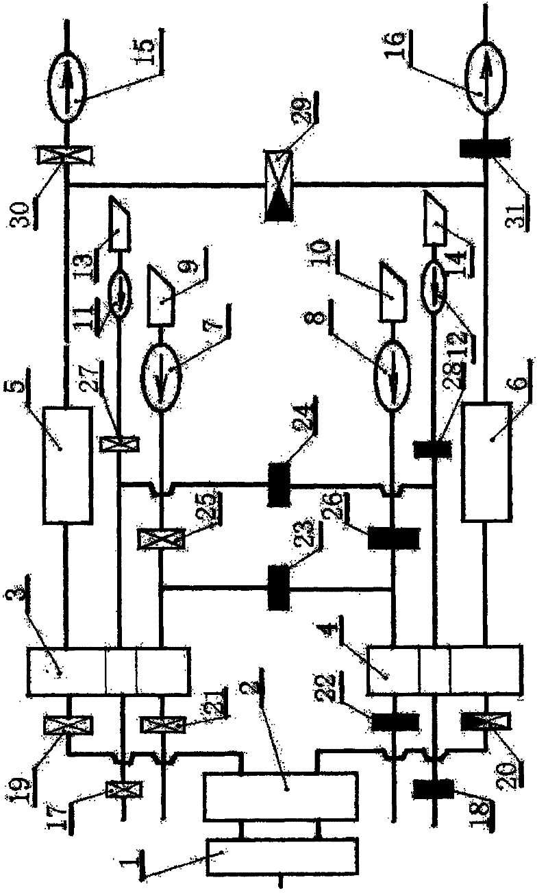
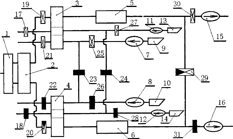
[0041] b. A side cold primary air inlet door (27), B side cold primary air inlet door (28), A side hot primary air outlet door (17), B side hot primary air outlet door (18), A side cold secondary air Entrance door (25), B side cold secondary air inlet door (26), A side hot secondary air outlet door (21), B side hot secondary air outlet door (22), cold primary air AB side liaison door ( 24) The AB side contact door (23) of the cold secondary air, the A side induced draft fan entrance door (30), and the B side induced draft fan entrance door (31) can be closed tightly;

[0042] c. The electric actuators of the flue gas inlet door (19) on the A si...


PUM


Abstract

The invention relates to a side-to-side thermal deashing method for a rotary air preheater. The method is realized in a way that: loads of a primary air fan, a blowing fan and a draught fan are totally poured to one side by utilizing the low load of a generator set at night; a primary air fan, a blowing fan and a draught fan on the other side are shut down to change the heat transfer situations of the high, medium and low temperature heat transfer elements on the fan shut-down side of the rotary air preheater; a small amount of controlled hot fume at the preheater inlet on the fan shut-down side is utilized to heat the heat transfer elements, and meanwhile, primary cold air and secondary cold air are prohibited to enter the rotary air preheater, so that the heat transfer elements on the fan shut-down side of the rotary air preheater are only heated without releasing heat while rotating; and when the temperature of the heat transfer elements is raised almost to the temperature of the hot air and far higher than the dew point of ammonium bisulfate, ash deposit becomes loosened and the falls off. The invention can be used for periodically and thoroughly removing ash deposit on the heat transfer elements in the medium and high temperature sections, so that the ash deposit can not become severe. The invention can enhance the operating efficiency of the station boiler and lower the station service power consumption rate, and has the advantages of high effectiveness, energy saving, low carbon and emission reduction.

Description

(1) Technical field: [0001] The invention relates to a side-split hot ash cleaning method for a rotary air preheater used in a power station boiler. Serious fouling of the heat transfer elements in the middle and low temperature sections of the rotary air preheater will make the exhaust gas temperature of the power station boiler abnormally increase, and the boiler efficiency will decrease; it will increase the power consumption of the fan and the power consumption rate of the plant. The rotary air preheater split-side hot ash cleaning method of the invention can periodically and completely remove the ash deposits of the heat transfer elements in the middle and low temperature sections, so that the ash deposits will not develop to a serious level, and the invention can improve the operation efficiency of the power station boiler, It is an effective energy-saving, low-carbon and emission-reduction technology to reduce the power consumption rate of the plant. (2) Background te...

Claims


Application Information

Patent Timeline
Patent Type & Authority Patents(China)
IPC IPC(8): F23J3/02F23L15/00
CPCY02E20/34
Inventor 章礼道
Owner 章礼道
Learn More