Ultrasonic guided wave device and method for detecting defect at rail bottom of steel rail at long distance

An ultrasonic guided wave, long-distance technology, which is applied in the analysis of solids using sonic/ultrasonic/infrasonic waves, and the analysis of materials using sonic emission technology.

Inactive Publication Date: 2011-05-04
NANCHANG HANGKONG UNIVERSITY
View PDF4 Cites 22 Cited by
  • Summary
  • Abstract
  • Description
  • Claims
  • Application Information

AI Technical Summary

Problems solved by technology

[0006] The purpose of the present invention is to provide a device and method for long-distance detection of rail bottom defects, so as to solve the problem that the rail bottom of the current line rail cannot be quickly and non-destructively detected

Method used


Image

  • Ultrasonic guided wave device and method for detecting defect at rail bottom of steel rail at long distance
  • Ultrasonic guided wave device and method for detecting defect at rail bottom of steel rail at long distance

Examples


Embodiment Construction

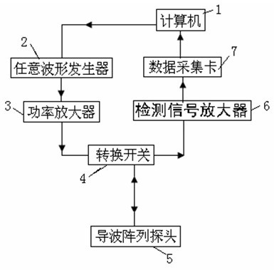
[0016] Such as figure 1 As shown, the present invention is realized in this way, the computer (1) is connected to the data acquisition card (7) and the arbitrary waveform generator (2), the data acquisition card (7) is connected to the detection signal amplifier (6), and the arbitrary waveform generator ( 2) Connect the power amplifier (3), the power amplifier (3) is connected to the transfer switch (4), and the transfer switch (4) is connected to the guided wave array probe (5) and the detection signal amplifier (6). The ultrasonic guided wave array probe (5) is composed of four low-frequency ultrasonic high-damping sub-probes. The low-frequency ultrasonic guided wave array probe (5) is placed vertically on the bottom side of the rail, and the center distance between the sub-probes is ,in is the guided wavelength. Each sub-probe is assembled in the probe box. The surface layer of the probe box is made of a steel plate with a certain thickness. When testing, hold the probe...


PUM


Abstract

The invention discloses an ultrasonic guided wave device for detecting a defect at the rail bottom of a steel rail at a long distance, which comprises a computer, a data acquisition card, a detection signal amplifier, an arbitrary waveform generator, a power amplifier, a change-over switch and a guided wave array probe. The ultrasonic guided wave device is characterized in that: the computer serves as a control center of the device, and controls the arbitrary waveform generator to generate a single-audio frequency signal of which central frequency is selected detection frequency; the single-audio frequency signal is transmitted to the guided wave array probe after passing through the power amplifier to excite guided waves of a vertical bending mode in the rail bottom of the steel rail; and under the regulation and control of the change-over switch, the guided wave array probe receives a defect reflection echo signal which is transmitted to the computer for processing and display after passing through the detection signal amplifier and the data acquisition card. The ultrasonic guided wave device realizes the rapid nondestructive detection of the defect at the rail bottom of the steel rail.

Description

technical field [0001] The invention relates to a device and method for detecting rail bottom defects, in particular to a long-distance detection device and method for rail bottom defects. Background technique [0002] At present, railway rails in various countries in the world mainly use ultrasonic automatic flaw detection vehicles for rails and hand-push ultrasonic flaw detection trolleys for rails. The technology of the rail ultrasonic flaw detection vehicle is to use a combination of 0-degree longitudinal wave probes and 37-degree, 45-degree, 70-degree shear wave probes to detect the rail head and rail waist. Technically, ultrasonic longitudinal and transverse waves belonging to the body wave mode are used. Detection method. The line rails are fixed on the sleepers through spring buckles and metal gaskets acting on the rail bottom plate. The rail bottom plate is very close to the ballast. In some remote sections, the rail bottom plate is even covered by ballast and san...

Claims


Application Information

Patent Timeline
Patent Type & Authority Applications(China)
IPC IPC(8): G01N29/04G01N29/14
Inventor 卢超黎连修
Owner NANCHANG HANGKONG UNIVERSITY
Why Eureka
Try Eureka