Vibration signal identification method for optical fiber perimeter system

A fiber optic perimeter and vibration signal technology, applied in the field of signal identification, can solve the problems of small number of characteristic parameters, high false alarm rate, and inability to distinguish various external vibration signals more accurately.

Active Publication Date: 2011-05-04
CHENGDU JIUZHOU ELECTRONIC INFORMATION SYSTEM CO LTD
View PDF3 Cites 65 Cited by
  • Summary
  • Abstract
  • Description
  • Claims
  • Application Information

AI Technical Summary

Problems solved by technology

[0003] The existing vibration signal identification method of the fiber optic perimeter system mainly uses the time-domain characteristics of the intrusion vibration signal for analysis, such as the vibration amplitude. Due to the small number of characteristic parameters for threshold judgment, it cannot distinguish various external vibration signals more accurately. Hence the high false positive rate

Method used


Image

  • Vibration signal identification method for optical fiber perimeter system
  • Vibration signal identification method for optical fiber perimeter system
  • Vibration signal identification method for optical fiber perimeter system

Examples


Embodiment Construction

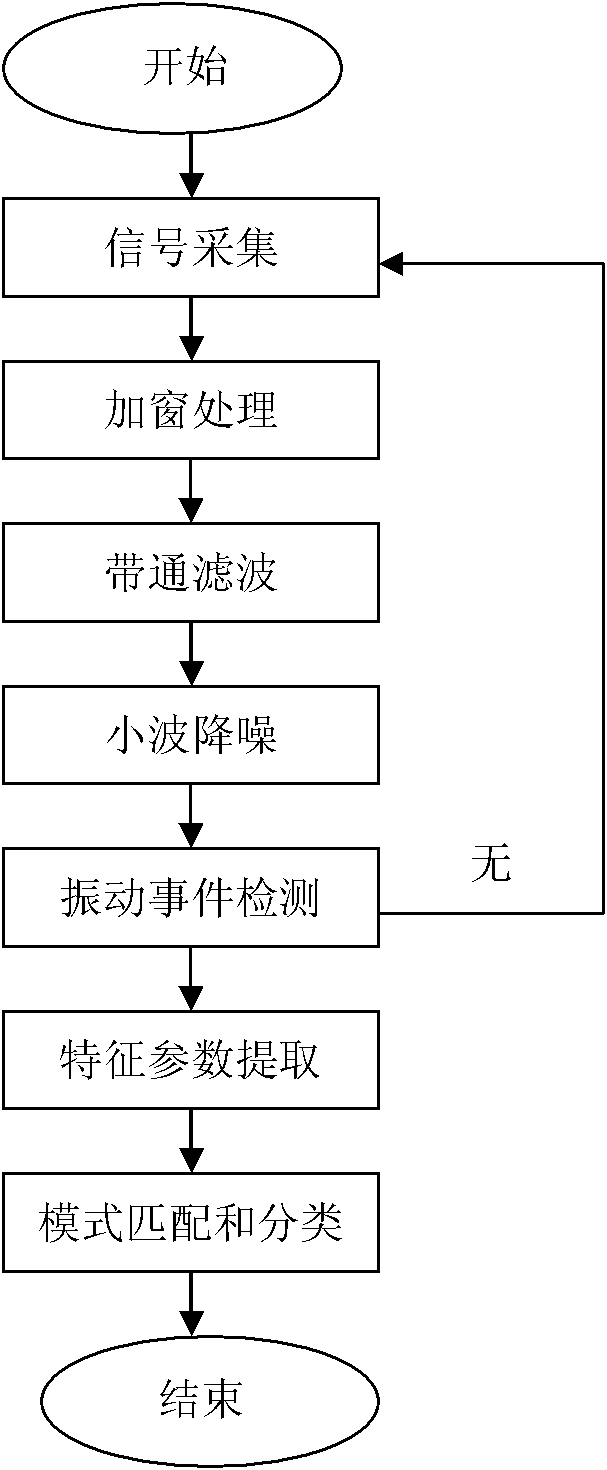
[0041] The present invention will be further described below in conjunction with the accompanying drawings and specific embodiments. A vibration signal identification method for an optical fiber perimeter system, comprising the steps of:

[0042] Step 1. Signal acquisition: the fiber optic perimeter system collects optical signals and converts them into original electrical signals S(n); the fiber optic sensors of the fiber optic perimeter system use armored communication optical cables, which can ensure that they are not affected by external changes. Under the influence of climate and harsh environment, it can still collect small vibrations. When the optical signal is transmitted in the optical fiber sensor, assuming that the optical fiber sensor has not received any interference or the transmission of light has not changed, then the phase of the optical signal will not change; when the optical fiber sensor is disturbed by motion or vibration, motion, vibration, The change of...


PUM


Abstract

The invention relates to a vibration signal identification method for an optical fiber perimeter system, which comprises the following steps of: (1) signal acquisition; (2) windowing treatment; (3) bandpass filtering; (4) wavelet denoising; (5) vibration event detection; (6) characteristic parameter extraction; and (7) pattern matching and classification. The invention has the advantages that the method introduces more characteristic parameters such as short-term energy E, short-time average magnitude M, short-term average zero-crossing rate Z, each wavelet decomposition scale detail signal energy Ew and vibration signal power spectrum P in comparison with the prior art, accurately judges the classification of external vibration signals, and reduces the probability of false alarm.

Description

technical field [0001] The invention belongs to signal identification technology, in particular to a vibration signal identification method of an optical fiber perimeter system. Background technique [0002] The fiber optic perimeter system is a security technology prevention system based on fiber optic sensing technology. The system is a warning network or security alarm system built using high-tech technologies such as laser, optical fiber sensing, and optical communication. It is a modern defense system that monitors and alerts emergencies that threaten public safety. The development of this technology not only reflects the needs of the modern anti-terrorist struggle, but also meets the needs of our country for perimeter alarms at this stage. The sensing optical fiber adopts armored communication optical cable, which can ensure that it can still collect small vibrations without being affected by the changeable climate and harsh environment of the outside world. When the...

Claims


Application Information

Patent Timeline
Patent Type & Authority Applications(China)
IPC IPC(8): H04B17/00H04B10/08H04B10/25
Inventor 谢箭
Owner CHENGDU JIUZHOU ELECTRONIC INFORMATION SYSTEM CO LTD
Why Eureka
Try Eureka