
Turbine device

A turbine and equipment technology, applied in the field of regulating turbine engines including such turbine equipment, can solve the problems of low efficiency fuel chemical energy utilization and achieve the effect of gas flow optimization

Inactive Publication Date: 2011-05-04
ERIKSSON DEV & INNOVATION
View PDF1 Cites 7 Cited by
  • Summary
  • Abstract
  • Description
  • Claims
  • Application Information

AI Technical Summary

Problems solved by technology

The disadvantage is usually low efficiency (i.e. utilization of fuel chemical energy)

Method used


Image

  • Turbine device
  • Turbine device
  • Turbine device

Examples


Embodiment Construction

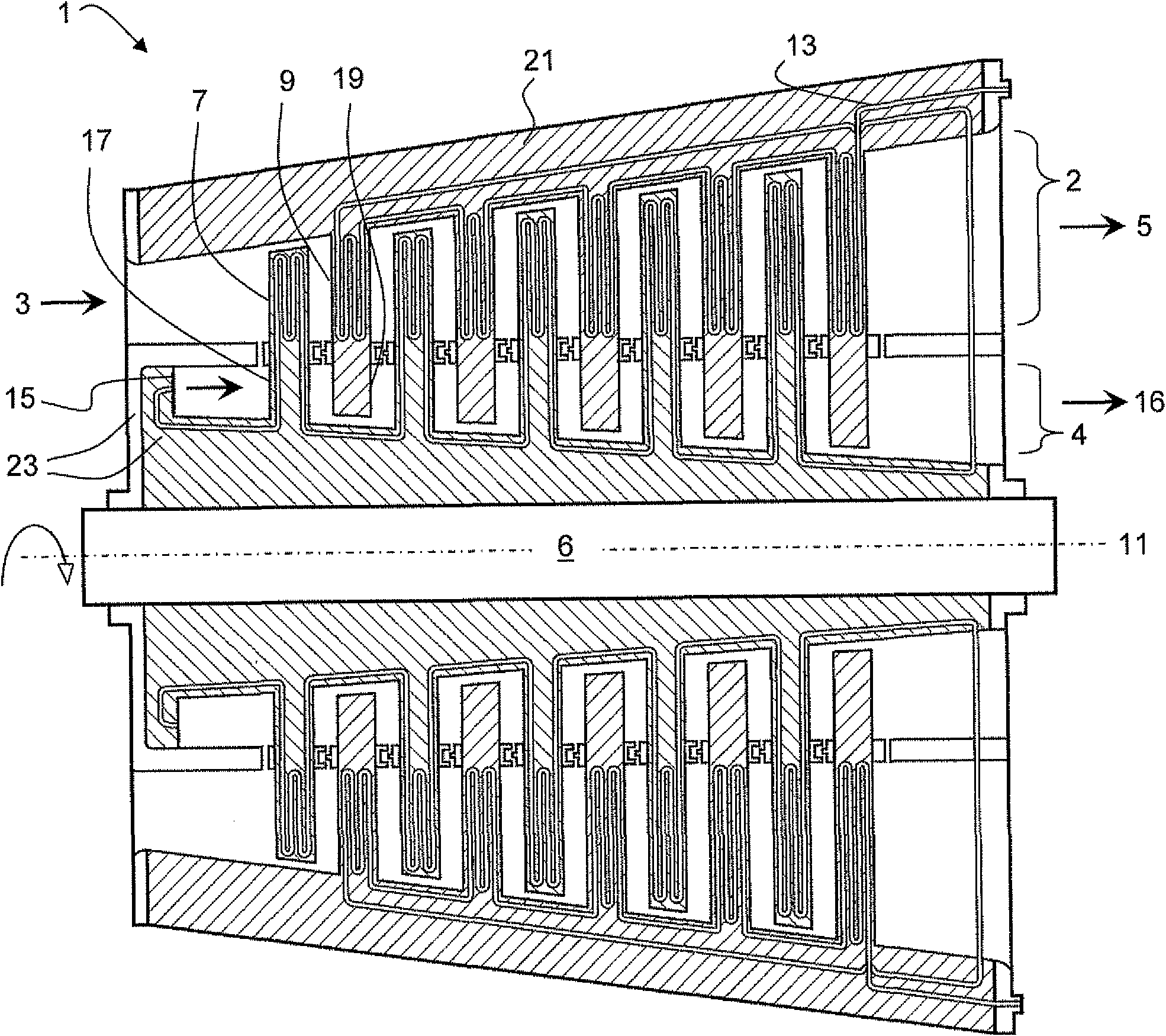
[0030] figure 1 A turbine plant 1 is shown comprising a gas turbine section 2 and a steam turbine section 4 , wherein the gas turbine section 2 and the steam turbine section 4 are arranged concentrically. This principle is disclosed in Swedish Patent No. SE530142 C2, US Provisional Application No. 60 / 969997 and PCT Application No. PCT / SE2008 / 050258.

[0031] Combustion gases enter (indicated by arrow 3 ) the gas turbine section 2 of the turbine plant 1 from the combustion chamber. exist figure 1 , the combustion gases pass through the gas turbine section 2 from left to right (as indicated by arrows 3 and 5 ), so that the gases drive the turbine shaft 6 by acting on a plurality of gas turbine rotor blades 7 . The gas turbine section 2 also includes a plurality of guide vanes or gas turbine stator blades 9 . The rotor blades 7 and the stator blades 9 are arranged at intervals along the longitudinal axis 11 of the turbine.

[0032] Fluid channels 13 are provided in the gas tu...


PUM


Abstract

The invention relates to a method for conversion of a gas turbine engine (37) to a turbine engine with a combined gas and steam turbine device (33). The invention also relates to improvements of a turbine device (1) comprising concentrically arranged gas and steam turbine portions (2, 4), especially with regards to the turbine blades (7, 17, 9, 19). Further, a method for regulating a turbine engine comprising such a turbine device is proposed.

Description

technical field [0001] The present invention relates to improvements in turbine installations comprising concentrically arranged gas turbine sections and steam turbine sections. The invention also relates to a method for regulating a turbine engine comprising such a turbine device. Background technique [0002] Gas turbine engines are used in many applications to convert the chemical energy of a fuel into mechanical energy. Among them, the gas turbine is driven by the air flow generated by the combustion of fuel. A gas turbine typically drives a compressor to compress air and provide an additional amount of oxygen to the combustor. [0003] In general, the advantage of a gas turbine engine is the engine's ability to deliver high power at low weight. The disadvantage is usually low efficiency (i.e. utilization of the chemical energy of the fuel). [0004] High efficiency turbine plants comprising concentric gas and steam turbine sections are disclosed in Swedish Patent No...

Claims


Application Information

Patent Timeline
Patent Type & Authority Applications(China)
IPC IPC(8): F02C3/10F02C6/02F02C6/18F01D5/18
CPCF02C3/10F01D5/187F02C6/02F02C6/18F05D2230/80F05D2260/2322Y02E20/14
Inventor T·埃里克松T·施特兰德
Owner ERIKSSON DEV & INNOVATION
Learn More