Wire harness

A wire harness and wire technology, applied in the field of wire harnesses, can solve problems such as peeling, unidentifiable wires, and difficult to identify wires

Inactive Publication Date: 2011-05-04
YAZAKI CORP
View PDF1 Cites 5 Cited by
  • Summary
  • Abstract
  • Description
  • Claims
  • Application Information

AI Technical Summary

Problems solved by technology

[0008] However, the marking of the wire harness described in the above-mentioned Patent Document 1 may be damaged due to external factors such as contact friction with exterior parts such as corrugated tubes, peripheral parts, or vehicle body panels during wiring work or assembly work. Peeling occurs
In addition, when thes

Method used


Image

  • Wire harness
  • Wire harness
  • Wire harness

Examples


Embodiment Construction

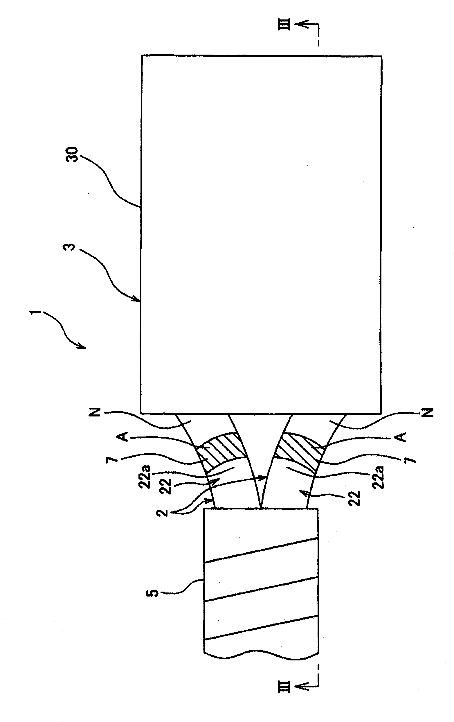
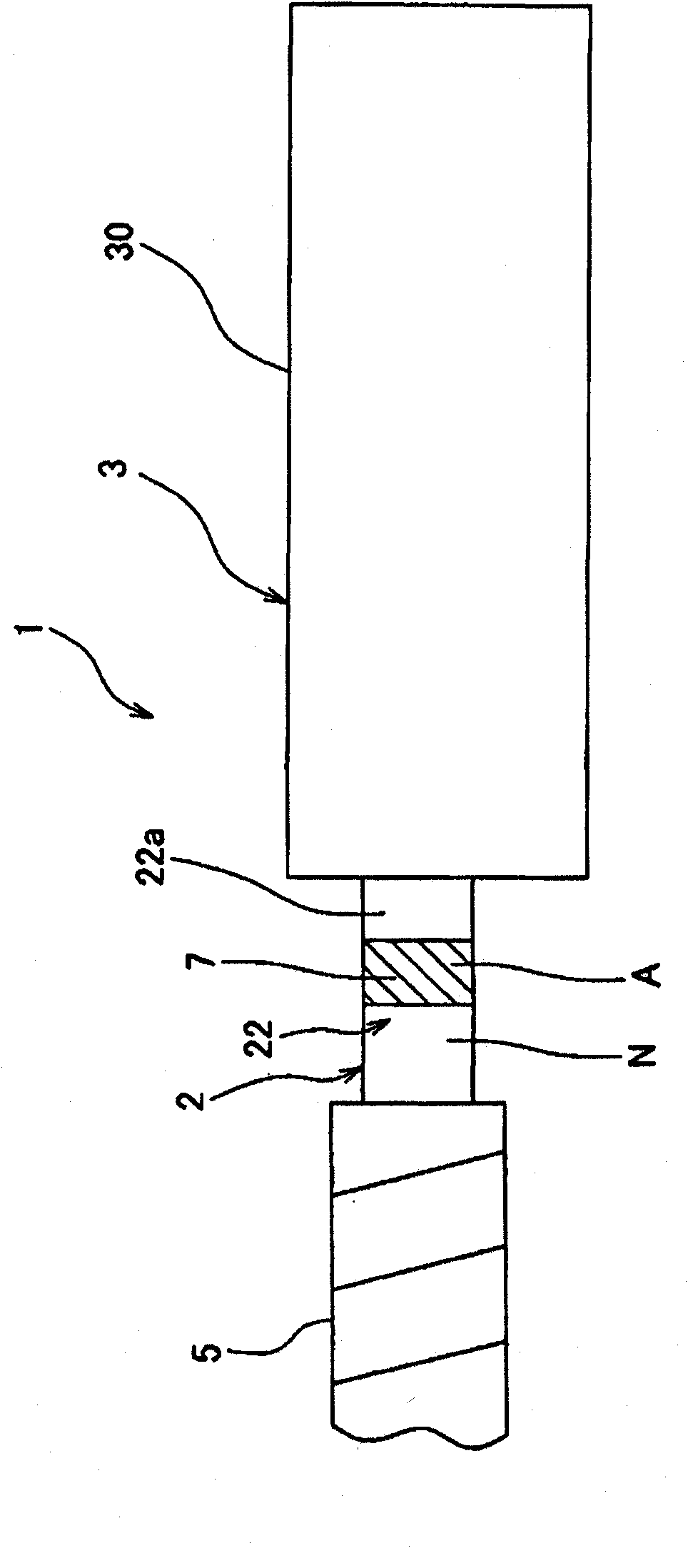
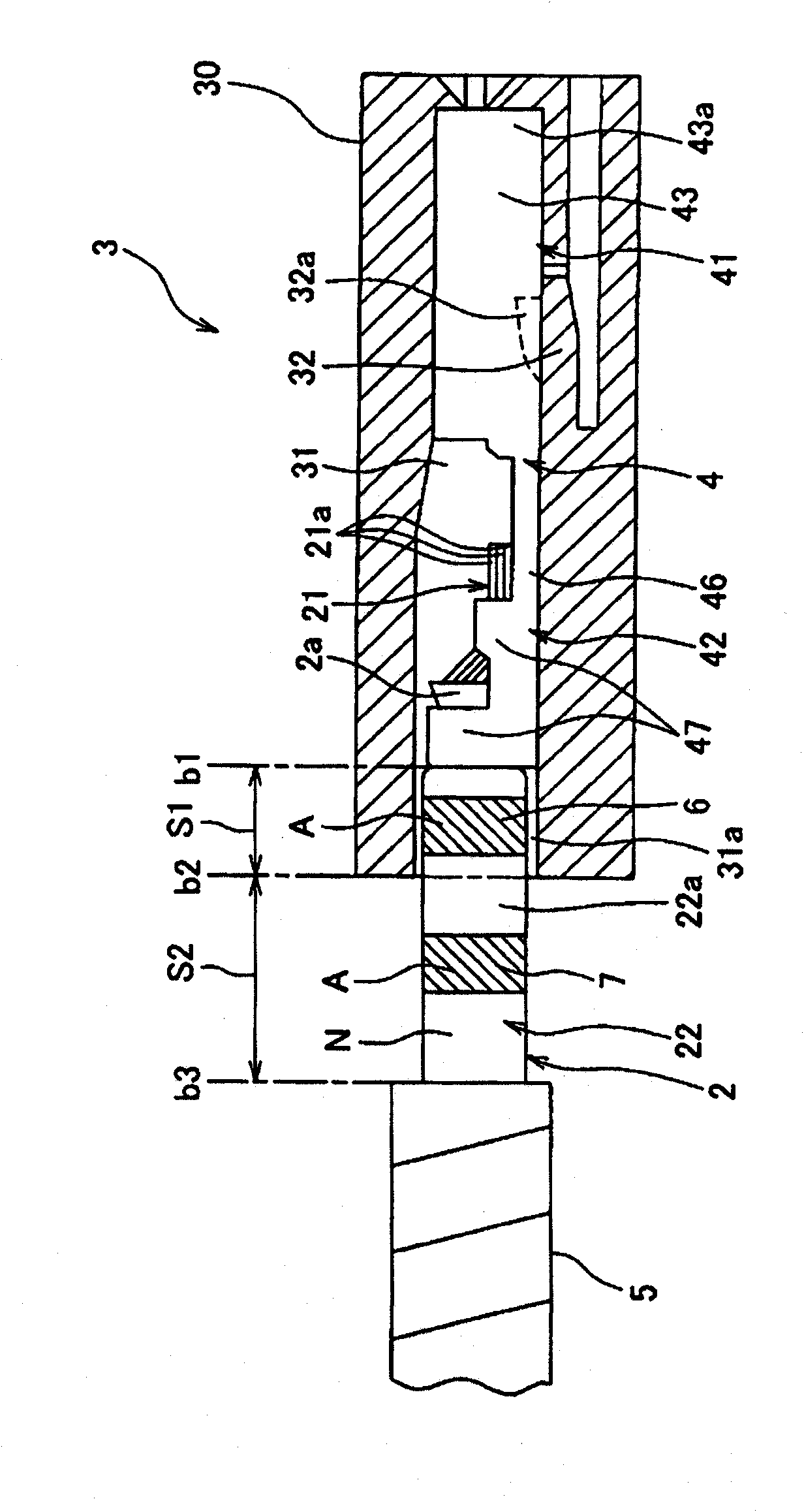
[0019] Below, refer to Figure 1 to Figure 3 A wire harness according to one embodiment of the present invention will be described. The wire harness 1 according to one embodiment of the present invention is mounted on, for example, an automobile which is a mobile body. Such as figure 1 As shown, the wire harness 1 has an electric wire 2, a connector 3, an exterior tape 5 as an exterior part, a first mark 6 ( image 3 ) and the second notation 7.

[0020] A plurality of electric wires 2 (two in the illustrated example) are provided. The electric wire 2 is a so-called covered electric wire 2 and is, for example, a low-voltage electric wire used for a low-voltage circuit in a motor vehicle. Such as image 3 As shown, the electric wire 2 has a conductive core wire 21 and an insulating covering portion 22 . The core wire 21 is formed by twisting a plurality of monofilaments 21a. The monofilament 21a constituting the core wire 21 is made of a conductive metal such as copper o...


PUM


Abstract

Provided is a wire harness which enables at least part of a mark formed on the outer surface of a covering portion to be prevented from peeling off and an electric wire to be identified. A wire harness (1) comprises an electric wire (2) and a connector (3). The electric wire (2) is provided with a conductive core wire (21) and an insulating covering portion (22) for covering the core wire (21). The connector (3) is attached to the end portion (2a) of the electric wire (2) and houses the end portion (2a) of the electric wire (2) therein. A first mark (6) and a second mark (7) are formed on the outer surface (22a) of the covering portion (22) of the electric wire (2). The first mark (6) is formed by coloring part of the outer surface (22a) of the covering portion (22) of the electric wire (2) housed in the connector (3) in a color (A) different from the single color (N) of the outer surface (22a). The second mark (7) is formed by coloring part of the outer surface (22a) of the covering portion (22) of the electric wire (2) exposed to the outside of the connector (3) in the same color (A) as that of the first mark (6).

Description

technical field [0001] The present invention relates to a wire harness including an electric wire having a conductive core wire, an insulating covering portion covering the core wire, and a connector accommodating an end portion of the electric wire inside. Background technique [0002] Various electronic devices are mounted on a mobile vehicle or the like. For this reason, the automobile or the like is equipped with a wire harness (for example, refer to Patent Document 1) to transmit electric power from a power source or the like or a control signal from a computer or the like to the electronic equipment. The wire harness described in Patent Document 1 includes at least a plurality of electric wires and a connector that is attached to the ends of the electric wires and accommodates the ends inside. [0003] The wires are so-called covered wires. The electric wire includes a conductive core wire and an insulating covering portion covering the core wire. For such electric ...

Claims


Application Information

Patent Timeline
IPC IPC(8): H01B7/00H01B7/36H02G1/06
CPCH01B7/361H01R43/28H02G2200/20
Inventor 杉村惠吾镰田毅杵塚健二
Owner YAZAKI CORP
Why Eureka
Try Eureka