Eureka AIR delivers breakthrough ideas for toughest innovation challenges, trusted by R&D personnel around the world.

Supersonic vibration countersinking device applied in pneumatic drilling

An ultrasonic vibration and air drilling technology, which is applied in the field of ultrasonic vibration spot facing devices, can solve the problems of poor portability of vibration devices, limited application of vibration technology, complex structure, etc., to improve processing accuracy and surface quality, reduce processing costs, reduce Effect of cutting force and cutting temperature

Inactive Publication Date: 2011-05-11
BEIHANG UNIV +1
View PDF4 Cites 13 Cited by
  • Summary
  • Abstract
  • Description
  • Claims
  • Application Information

AI Technical Summary

Problems solved by technology

However, the previous vibratory processing devices have complex structures and large volumes, and they are all applied to machine tools or various processing centers.
Therefore, the portability of the vibration device is poor, which limits the application of vibration technology in light and portable hand tools, especially in the current aircraft skin assembly site, it is impossible to apply the advantages of vibration technology to ordinary air drills to process a large number of difficult-to-machine laminated materials with high precision fastener hole

Method used


Image

  • Supersonic vibration countersinking device applied in pneumatic drilling
  • Supersonic vibration countersinking device applied in pneumatic drilling
  • Supersonic vibration countersinking device applied in pneumatic drilling

Examples


Embodiment Construction

[0040] The present invention will be further described in detail below in conjunction with the accompanying drawings.

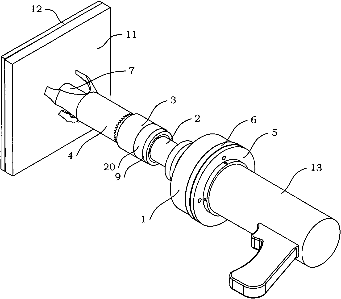
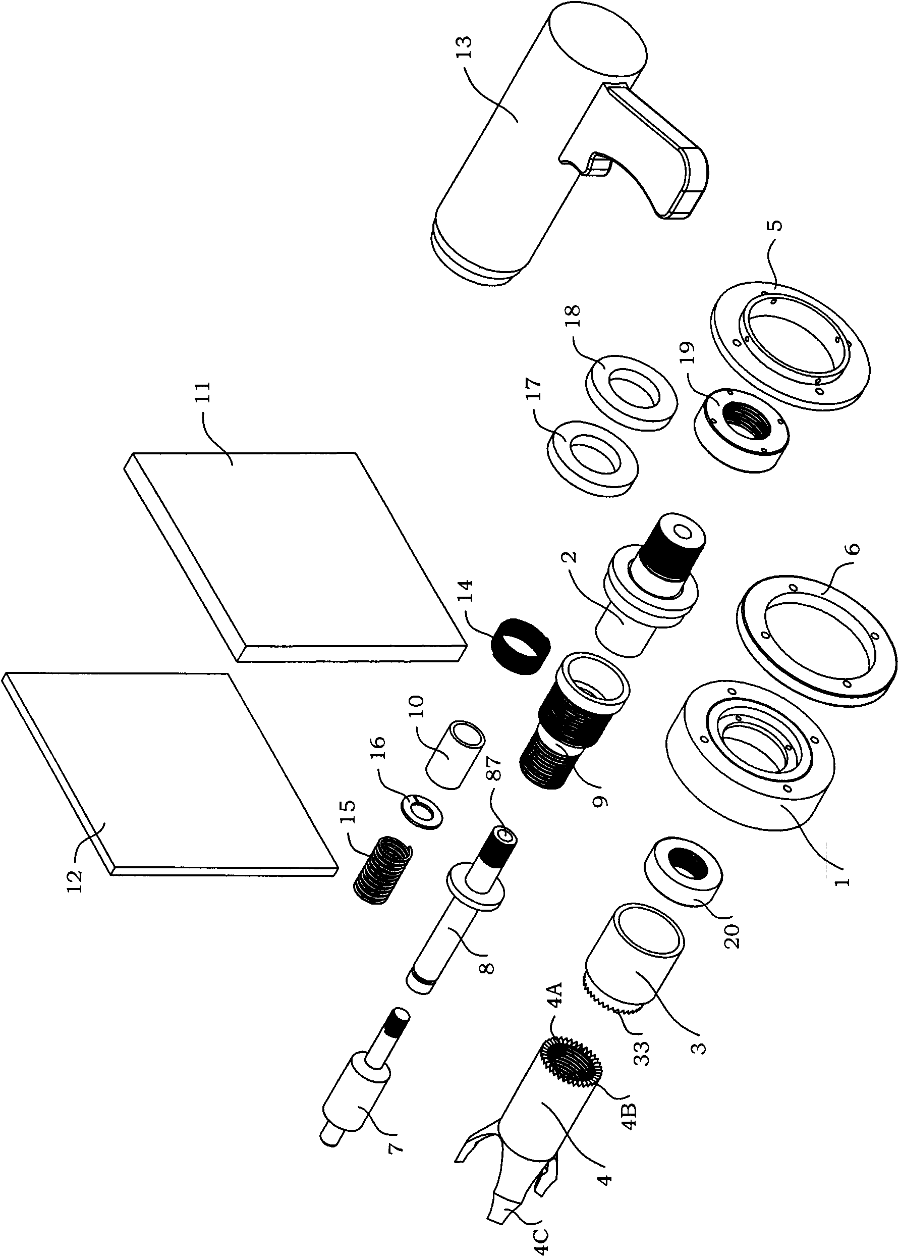
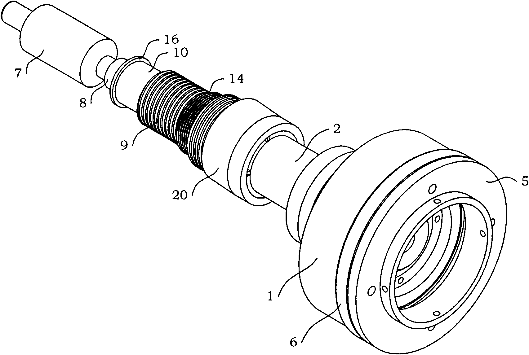
[0041] see figure 1 , Figure 1A , Figure 1B , Figure 1C As shown, an ultrasonic vibration drilling device of the present invention applied to an air drill includes a slip ring 1, a front cover plate 2, a shaft sleeve 3, a tripod bracket 4, a flange plate 5, a retaining ring 6, a countersink 7. Central shaft 8, center sleeve 9, bushing 10, air drill 13, outer spring 14, inner spring 15, snap ring 16, B ceramic sheet 17, A ceramic sheet 18, rear cover plate 19, snap ring 20. In the present invention, the shell of the air drill 13 is connected to the flange 5 , and the main shaft of the air drill 13 is connected to the internal thread hole 21 of the front cover plate 2 . The spot facing tool 7 is connected to the mounting section 86 of the central shaft 8 . In order to realize the mobility at the construction site, the air drill 13 adopts a manual air dr...


PUM


Abstract

The invention discloses a supersonic vibration countersinking device applied in pneumatic drilling. The device comprises a slide ring, a front cover plate, a shaft sleeve, a three-legged bracket, a flange disc, a retaining ring, a countersink, a central shaft, a central sleeve, a lining, a pneumatic drill, an external spring, an internal spring, a clamp spring, a ceramic plate B, a ceramic plate A, a rear cover plate and a clamp ring. A main shaft of the pneumatic drill is connected with an internal threaded hole on the front cover plate, the ceramic plate B, the ceramic plate A and the rear cover plate are mounted at one end of the front cover plate, the other end of the front cover plate is connected with one end of the central shaft, the central shaft is sleeved in the central sleeve, and the other end of the central shaft is connected with the countersink; and an internal ring of the slide ring is mounted on the external edge of the rear cover plate, a connecting ring is arranged between an external ring of the slide ring and the flange disc, a casing of the pneumatic drill is connected with the flange disc; and the three-legged bracket, the shaft sleeve and the clamp ring are sleeved on the central sleeve, and the three-legged bracket can ensure that the countersink is perpendicular to the surface of a workpiece to be processed. The supersonic vibration drilling device provided by the invention can be applied in the tight high-precision countersinking of carbon fiber composite material of airplane skin as well as of large ports of titanium-alloy laminated fasteners.

Description

technical field [0001] The invention relates to an ultrasonic vibrating spot facing device, more particularly, to an ultrasonic vibrating spot spotting device applied to an air drill. The ultrasonic vibration drilling device is more suitable for high-precision compact spot-face machining of large holes of aircraft skin carbon fiber composite materials and titanium alloy laminated fasteners. Background technique [0002] Ultrasonic vibration cutting is a cutting method that adds an ultrasonic vibration to the tool to make the original continuous cutting process intermittent and has a special cutting effect. It was first proposed by Japanese scholars. Ultrasonic vibration cutting has the unique advantages of reducing cutting force and cutting temperature, improving surface quality and shape and position accuracy. However, the previous vibration processing devices have complex structures and large volumes, and they are all applied to machine tools or various processing centers...

Claims


Application Information

Patent Timeline
IPC IPC(8): B23B35/00
Inventor 张德远姜兴刚刘静秦龙刚陈允全陈丽丽徐菁
Owner BEIHANG UNIV
Why Eureka
Eureka Blog
Learn More