Electric brake system, especially electromechanical brake system

A brake system and electric technology, applied in the direction of brake safety system, brake transmission device, brake action activation device, etc., can solve the problems of control unit failure and entry, and achieve the effect of avoiding failure

Active Publication Date: 2011-05-11
ROBERT BOSCH GMBH
View PDF6 Cites 5 Cited by
  • Summary
  • Abstract
  • Description
  • Claims
  • Application Information

AI Technical Summary

Problems solved by technology

However, if the low voltage state is assumed because the load current is too high for the current state of charge of the energy store, the supply voltage drops below a threshold value, and all control units of the brake circuit fail or go to low voltage reset

Method used


Image

  • Electric brake system, especially electromechanical brake system
  • Electric brake system, especially electromechanical brake system

Examples


Embodiment Construction

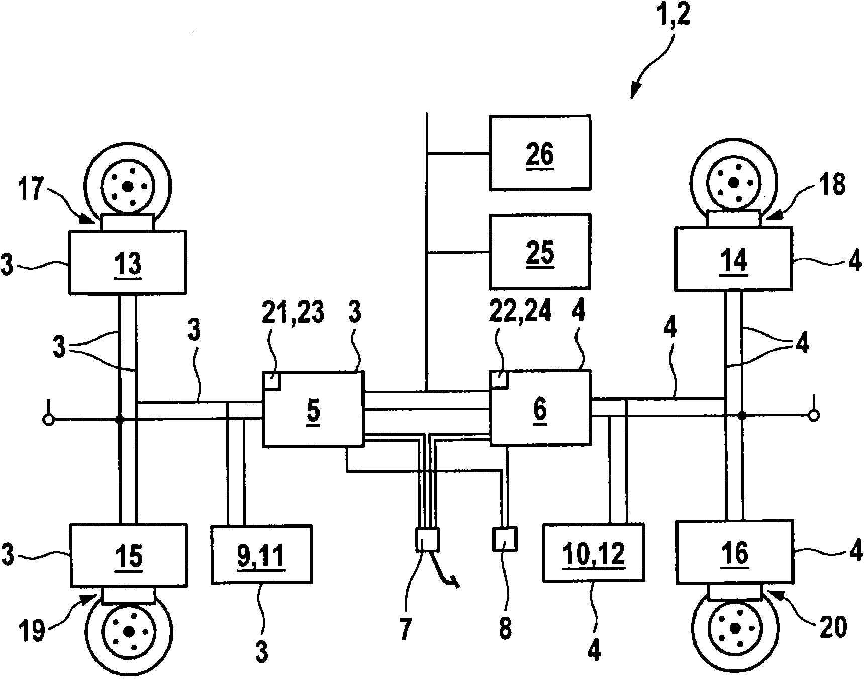
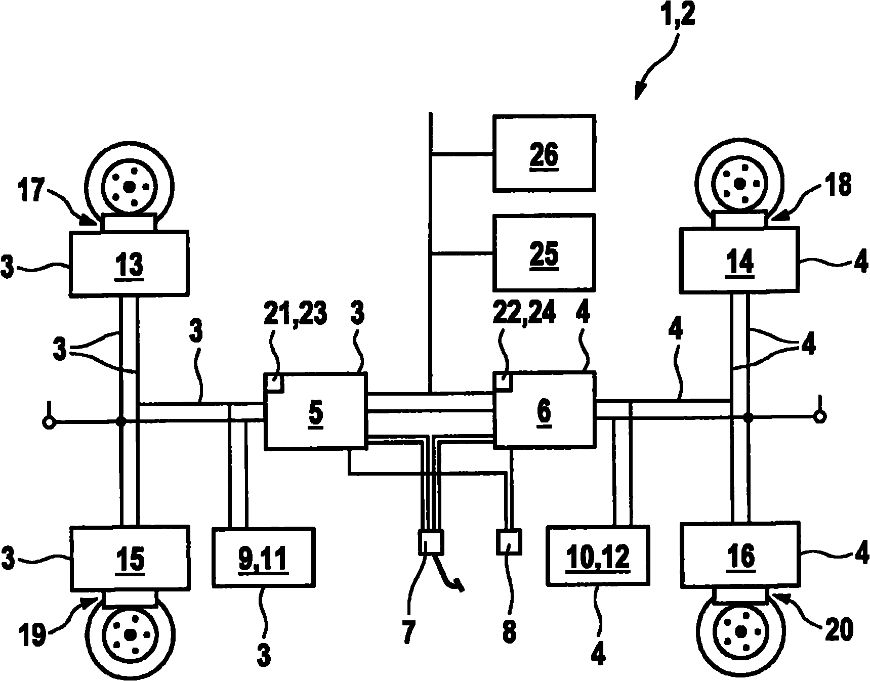
[0016] The drawing shows a schematic illustration of an electric braking system 1 , which is designed as an electromechanical braking system 2 . The electric brake system 1 has two mutually independent brake circuits, the components of which are denoted here by the reference numerals 3 and 4 in the continuation. Each brake circuit 3, 4 has a first control unit 5 or 6, which detects a braking request of the driver of the vehicle having the braking system 1. To this end, the control units 5 and 6 each receive input signals from the sensor systems of the brake pedal 7 and the parking brake 8 . The control units 5 , 6 preferably determine the braking force distribution and / or the braking torque regulation or tensioning force regulation as a function of the braking requirements. Furthermore, each brake circuit 3 and 4 has an electrical energy supply 9 , 10 in the form of an energy store 11 , 12 . The control units 5 and 6 form a redundant mechanism for detecting the driver's wish...


PUM


Abstract

The invention relates to an electric brake system (1) for vehicle, specifically relates to an electromechanical brake system (2), comprising at least one brake circuit (3, 4). The brake circuit comprises at least one first control unit (5, 6) for converting the braking requirement of a driver to a triggering signal, and second control units (13,15; 14,16) respectively matched to wheel brakes (17,19; 18,20) of a vehicle and processing the triggering signal. The first control unit (5,6) comprises at least one local energy memory (21,22).

Description

technical field [0001] The invention relates to an electric braking system, in particular an electromechanical braking system, for a vehicle, which has at least one brake circuit comprising at least one brake circuit for actuating a braking request from the driver of the vehicle. A first control unit which converts the trigger signal and a second control unit which is respectively assigned to the wheel brakes of the vehicle and which processes the trigger signal. [0002] Furthermore, the invention relates to a method for operating an electric braking system. Background technique [0003] An electric braking system and a method for operating the braking system are known, for example, from laid-open documents DE 101 18 263 A1 and from laid-open document DE 198 26 131 A1. In such a so-called decentralized electric braking system, at least one brake circuit is provided, which includes a first control unit and a plurality of second control units. In this case, the first contro...

Claims


Application Information

Patent Timeline
Patent Type & Authority Applications(China)
IPC IPC(8): B60T13/74B60T8/17B60T17/22
CPCB60T13/741B60T7/042
Inventor R·魏贝尔勒
Owner ROBERT BOSCH GMBH
Why Eureka
Try Eureka