Drop test bed with speed controllable rotation driving mechanism

A technology of a test bench and a test bench, which is applied in the field of a type of test device, can solve the problems that the accuracy of the tire contact speed is difficult to guarantee, and achieve the effects of avoiding the loss of the wheel speed, occupying a small space, and having a compact structure

Active Publication Date: 2011-05-11
NANJING UNIV OF AERONAUTICS & ASTRONAUTICS
View PDF4 Cites 15 Cited by
  • Summary
  • Abstract
  • Description
  • Claims
  • Application Information

AI Technical Summary

Problems solved by technology

[0003] Purpose of the present invention: the present invention has simple and compact structure, convenient installation and low cost, which better solves the problem that the accuracy of the tire contact speed caused by the loss of wheel rotation is difficult to guarantee, and improves the test accuracy

Method used


Image

  • Drop test bed with speed controllable rotation driving mechanism
  • Drop test bed with speed controllable rotation driving mechanism
  • Drop test bed with speed controllable rotation driving mechanism

Examples


Embodiment Construction

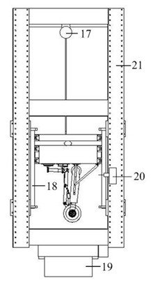
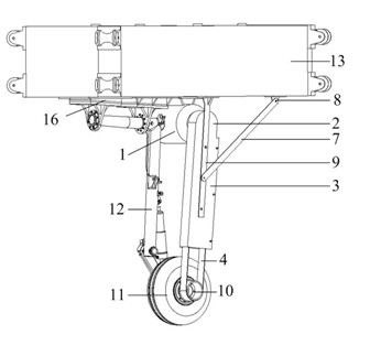
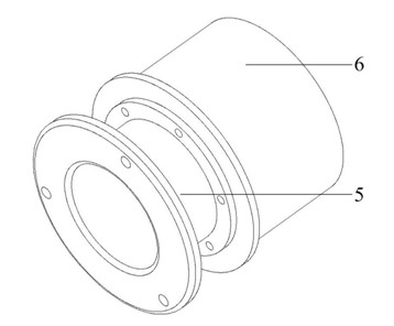
[0014] The present invention is a drop shock test bench with a controllable speed and rotation mechanism, which includes a test bench, a hanging basket and a landing gear. The motor 1 is installed on the bottom plate of the gondola 13 by bolts, and a wheel belt wheel 10 is installed on the landing gear wheel 11. The wheel belt wheel 10 is composed of a belt wheel 5 and a connecting hub 6, and the connecting hub 5 passes through the wheel hub bolt 14 To fix, for easy installation, install the connecting hub 5 first, and then install the pulley 6 on the connecting hub 5. Make sure that the motor pulley 2 and the pulley 6 are parallel to each other. The belt 4 is a common flat belt to prevent the belt 4 from slackening. In case of injury, a belt box 3 is installed on the periphery of the belt, and the belt box 3 is fixed on the bottom plate of the hanging basket 13 through a bracket 9. During the test, the energized motor pulley 2 rotates, and the motor pulley 11 rotates through t...


PUM


Abstract

The invention discloses a drop test bed with a speed controllable rotation driving mechanism, which comprises a test bed rack, a hanging bracket and an undercarriage, wherein the hanging bracket is arranged in the test bed rack and can creep down along sliding ways of the test bed rack; and the undercarriage is fixed at the lower end of the hanging bracket. An electromotor is also arranged at the lower end of the hanging bracket. An electromotor belt pulley is connected to an output shaft of the electromotor. An airplane wheel belt pulley synchronous with an airplane wheel is arranged on the airplane wheel of the undercarriage, and is in transmission with the electromotor belt pulley through a belt. A travel switch is also arranged on the sliding way of the test bed rack, and controls the electromotor to stop when the airplane wheel is landed. The drop test bed with the speed controllable rotation driving mechanism has a light and compact structure, simple layout and reliable performance, and is convenient to operate.

Description

Technical field [0001] The invention relates to a drop shock test bench, belonging to a type of test device, which can be applied to the drop shock test of the aircraft landing gear and the tire test. Background technique [0002] The landing gear drop shock test is a key part of the landing gear design. Through the test, the buffer filling parameters are adjusted to improve the buffer efficiency, and it is checked whether the structural strength and rigidity of the landing gear meet the design requirements. The landing gear ground drop test needs to simulate the real movement process of the landing gear when the aircraft is landing, and one of the most important items is the simulation of the horizontal landing speed of the aircraft. There are two usual simulation methods. One is to build a high-speed rail-carrying scooter. This equipment simulation method is the closest to the real situation. However, the equipment requires a large site, complex technology, and difficult insta...

Claims


Application Information

Patent Timeline
Patent Type & Authority Applications(China)
IPC IPC(8): G01M7/08
Inventor 聂宏安红辉薛彩军张明
Owner NANJING UNIV OF AERONAUTICS & ASTRONAUTICS
Why Eureka
Try Eureka