
Disk grabbing device

A grabbing device and disc technology, which is applied in the direction of record information storage, instruments, etc., can solve the problems of low production efficiency, affecting the yield rate, and affecting the production process, so as to achieve accurate and reliable grabbing process, improve yield rate, and ensure The effect of cleanliness

Inactive Publication Date: 2011-05-11
HENAN KAIRUI DIGITAL
View PDF3 Cites 4 Cited by
  • Summary
  • Abstract
  • Description
  • Claims
  • Application Information

AI Technical Summary

Problems solved by technology

[0003] When processing different processes, it is necessary to use the grabbing device to realize the transfer of the disc, so as to realize the transfer of the disc between different processing equipment, thereby forming a smooth processing production line. However, the existing grabbing device is generally Use the suction nozzle or ring suction nozzle to absorb the surface of the central area of ​​the disk to realize the transfer of the disk. During this process, the suction nozzle directly touches the surface of the disk, and because the material of the suction nozzle is mostly rubber, it is easy to absorb dust. When the suction nozzle directly contacts the surface of the disc, it is very easy to stick dust to the disc, affecting the cleanliness of the disc, thus affecting the yield rate. At the same time, the suction nozzle needs to be stopped regularly for replacement and cleaning, which affects the production process and production efficiency not tall

Method used


Image

  • Disk grabbing device
  • Disk grabbing device
  • Disk grabbing device

Examples


Embodiment Construction

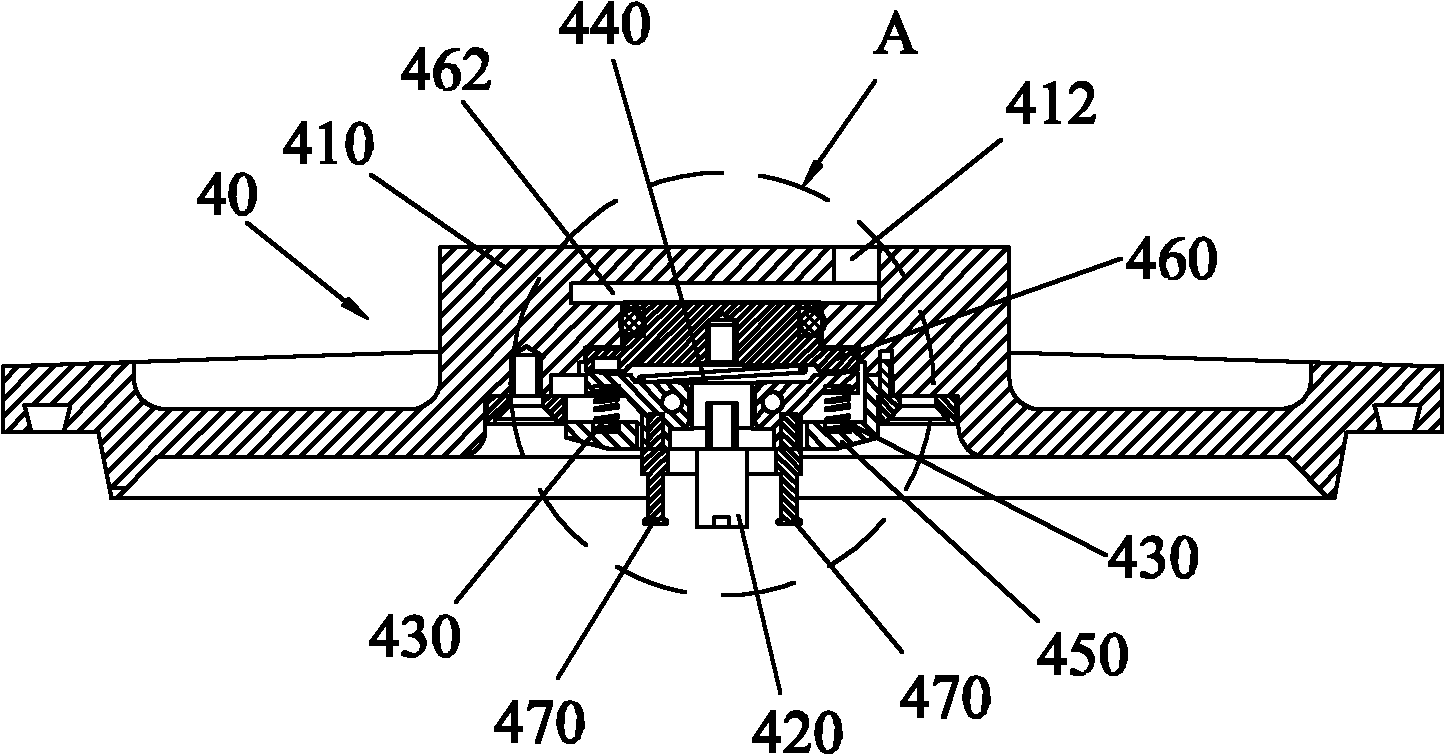
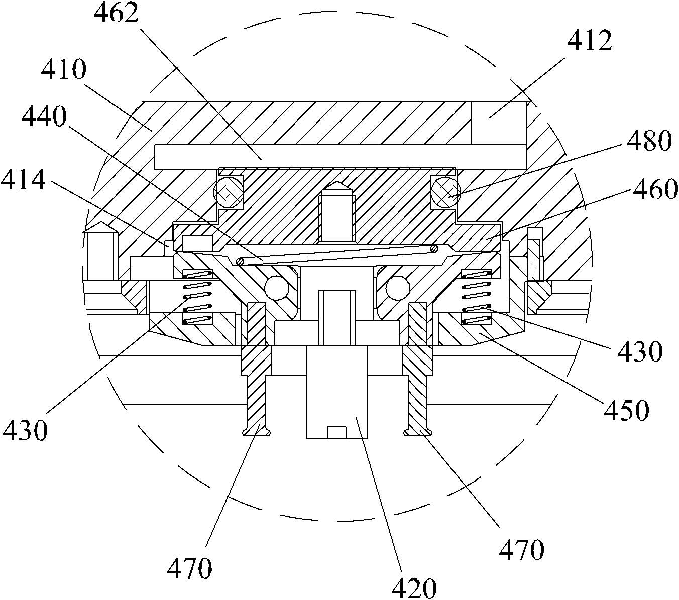
[0020] In order to describe the technical content and structural features of the present invention in detail, the following will be further described in conjunction with the embodiments and accompanying drawings, wherein the same reference numerals in different drawings represent the same components. As mentioned above, the disc grabbing device provided by the present invention uses three claw arms to pick and place the disc through the central hole of the disc, avoiding contact with the upper and lower surfaces of the disc, and ensuring the cleanliness of the disc transfer on the station , improve the disc yield, and the grasping process is accurate and reliable, ensuring the smoothness of the disc processing line and improving production efficiency.

[0021] refer to figure 1 and Figure 5 , the disc grabbing device of the preferred embodiment of the present invention is used for positioning, handling and transferring discs 20, the discs 20 are carried on the tray 10, and t...


PUM


Abstract

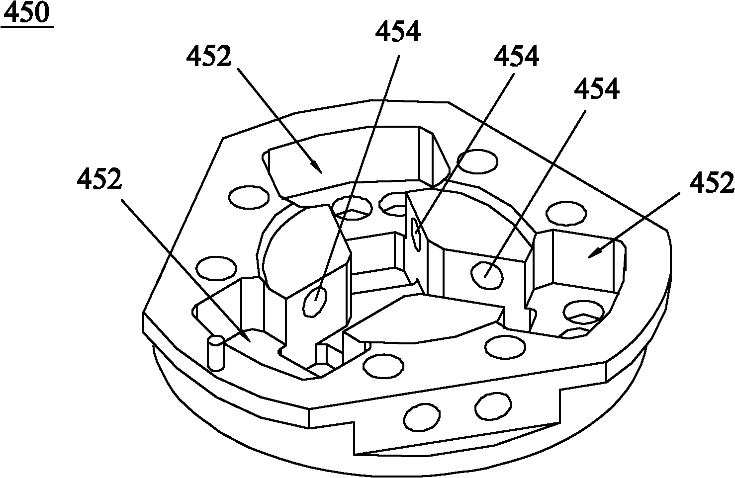
The invention discloses a disk grabbing device which comprises a locating mechanism and a grabbing mechanism that are mutually matched, wherein the grabbing mechanism comprises a foundation support, a thimble, elastic elements, a permanent seat, a piston and three jack catches, the foundation support is arranged right above a tray and provided with an installing groove, the permanent seat is fixed in the installing groove, the piston is accommodated in the installing groove, the jack catches are uniformly distributed at 60 degrees and arranged in the foundation support in a pin-jointed way, each jack catch is provided with a button arm and a claw arm which form a lever, the claw arm is provided with a hook part for grabbing a disk, the bottom of the piston supports against the button arm, an air pressure cavity is formed between the piston and the installing groove, the elastic elements are respectively arranged between the piston and the claw catches and between the permanent seat and the claw catches, when the disk is put down, air pressure is charged, the piston moves downwards, the elastic elements are compressed, the three claw catches are folded up; and when the disk is taken, the air pressure is released, the elastic elements restore and stretch out, the piston moves upwards, and the three claw catches unfold. The disk grabbing device disclosed in the invention has the advantages of higher cleanness and capability of effectively improving the yield and the production efficiency.

Description

technical field [0001] The invention relates to an optical disc production system, and more particularly to a grabbing device for handling and transporting optical discs. Background technique [0002] With the continuous expansion of the information capacity of optical storage media, the production technology of optical storage media is also developing vigorously. Taking the production system of BD50 and DVD9 as examples, the production of BD50 system: injection molding of 1.1 After the mm thick substrate is cooled by the cooling belt, the total reflection layer is sputtered, and then the 23um space layer glue layer is spin-coated, UV cured, and then the 2um glue replication layer is spin-coated, and then enters the disc grabbing device to copy the information Layer, then sputtering semi-reflective layer, then spin-coating 75um cover layer, UV curing, then spin-coating 2um hardcoat protective layer, UV curing, reverse dish, sputtering SiN waterproof layer, online detection a...

Claims


Application Information

Patent Timeline
IPC IPC(8): G11B17/022
Inventor 杨明生范继良刘惠森杨杨陈贵青邢三军蓝海锋
Owner HENAN KAIRUI DIGITAL
Learn More