
Anti-bouncer for circuit breaker

An anti-bounce and circuit breaker technology, applied in circuits, contacts, electrical components, etc., can solve the problems of device failure, large electric repulsion, and small electric repulsion, and achieve the effects of simple structure, reliable performance and long mechanical life.

Inactive Publication Date: 2011-05-11
XI AN JIAOTONG UNIV
View PDF2 Cites 21 Cited by
  • Summary
  • Abstract
  • Description
  • Claims
  • Application Information

AI Technical Summary

Problems solved by technology

This known anti-bounce device can sometimes play the role of anti-bounce when short-circuiting large currents, but the reliability is not high; it can hardly work when short-circuiting small currents
The main reasons are as follows: Compared with the tension and compression spring, the error of the reset torsion spring is not easy to control. If the parameter of the torsion spring is too large, the locking part will not swing downward enough. Before the gear collides with the stop gear, the device will fail; the current value of the circuit breaker to break the short-circuit current is different, the short-circuit current is large, the electric repulsion is large, and the opening speed is fast, the short-circuit current is small, the electric repulsion is small, Therefore, the opening speed is slow. Under different opening speeds, the downward swing of the locking member is different, so this kind of anti-bounce device will not work at certain opening speeds.
In addition, this kind of anti-bounce device is fixed on the transmission part that rotates with the main shaft, which will inevitably affect the opening and closing speed of the circuit breaker; in addition, the shaft pin and limit rod required by this kind of anti-bounce device cannot be made larger, Therefore the mechanical life cannot be guaranteed
[0004] To sum up, the anti-bounce device in the prior art is not reliable, and cannot meet the requirement of preventing the moving contact of the circuit breaker from bouncing under various current values.

Method used


Image

  • Anti-bouncer for circuit breaker
  • Anti-bouncer for circuit breaker
  • Anti-bouncer for circuit breaker

Examples


Embodiment Construction

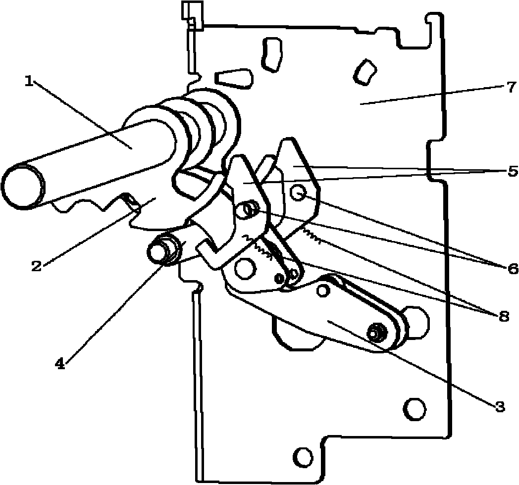
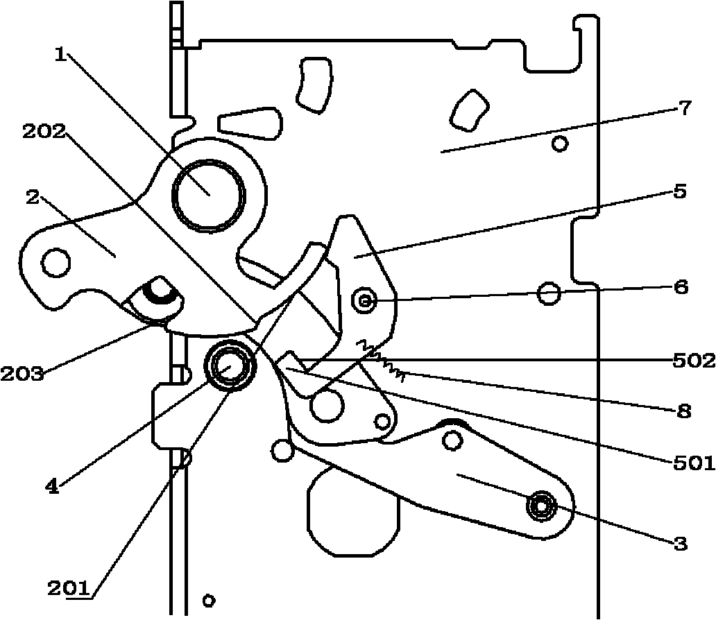
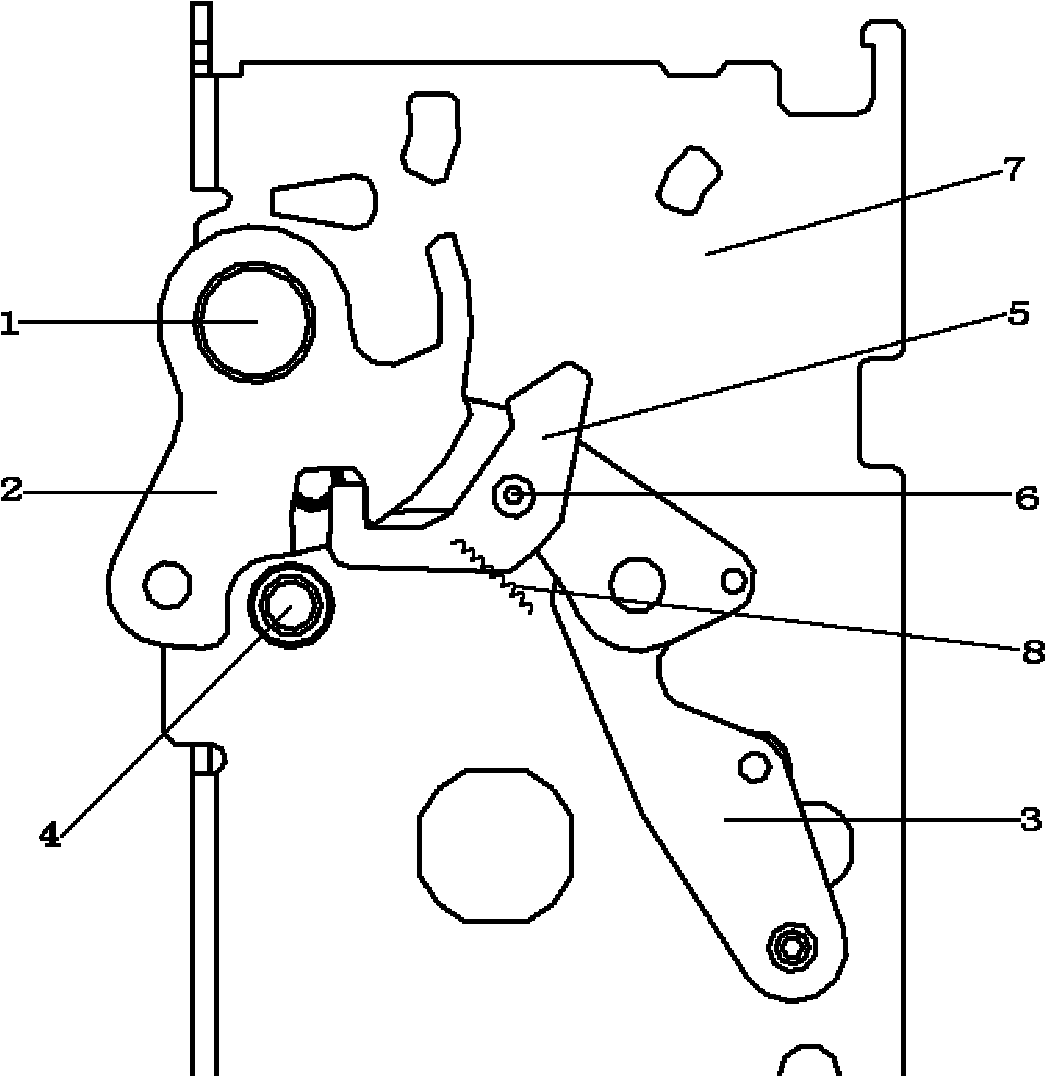
[0017] refer to figure 1 , 2 , 3, and 4, the present invention includes a main shaft 1, a transmission member 2, a connecting rod system 3, a stopper 4, a hook rod 5, a shaft pin 6, a side plate 7, and a return spring 8; the side plate 7 is The side plate of the circuit breaker mechanism is fixed on the circuit breaker frame, the main shaft 1 passes through the hole on the side plate 7 and can rotate around the hole on the side plate 7; the transmission part 2 and the main shaft 1 are fixed and rotate with the main shaft 1, and the transmission part 2. The left side is connected with the moving contact system of the circuit breaker; the stopper 4 passes through the hole on the side plate 7 and is fixed on the side plate 7 by riveting, and its function is to limit the rotation of the main shaft 1 and the transmission part 2; the connecting rod system 3 Connected with the main shaft 1 to drive the circuit breaker to open and close; the shaft pin 6 is fixed on the side plate 7 b...


PUM


Abstract

The invention discloses an anti-bouncer for a circuit breaker, belonging to the field of low-voltage circuit breakers. The anti-bouncer comprises a main shaft, a driving component, a link system, a backstop, a hook rod, a shaft pin, a side plate and a return spring, wherein the side plate is fixed on a shell frame of the whole circuit breaker and plays the effects of supporting and spacing other components; the main shaft passes through a spacing hole in the side plate and is rotatable; the driving component is fixed on the main shaft; the shaft pin is fixed on the side plate; and the hook rod passes through the shaft pin and can rotate around the shaft pin. The invention is characterized in that when the circuit breaker trips, an inclined plane on the driving component collides with the hook rod, so that the hook rod obtains initial speed for clockwise rotation, and the hook rod continues to rotate under the inertia force and enters a groove on the driving component, thereby hooking the driving component and achieving the anti-bounce effect. The device has simple structure, reliable performance and long mechanical service life, and can effectively prevent the bounce of contacts to improve the performance of the circuit breaker.

Description

technical field [0001] The invention belongs to the technical field of low-voltage electrical appliances, and relates to an anti-bounce device of a circuit breaker. Background technique [0002] Since the speed of the circuit breaker opening is very fast, and the circuit breaker mechanism is made of rigid materials, the bouncing phenomenon is serious when the circuit breaker is opening. After the moving and static contacts of the circuit breaker reach the maximum opening distance, there will be a large rebound, and the rebound range can reach half of the opening distance, and even the moving and static contacts will re-contact. This kind of bouncing will cause the arc to not be extinguished in time. Even the arc reignites, seriously affecting the breaking ability of the circuit breaker. [0003] Although the industry has been working on finding a reliable and simple way to implement the anti-bounce function, there has been no particularly good solution. The known anti-boun...

Claims


Application Information

Patent Timeline
IPC IPC(8): H01H71/10H01H1/50
Inventor 胡正勇荣命哲吴翊黄蓉蓉杨飞
Owner XI AN JIAOTONG UNIV
Learn More