Zero-current switched-off solid state relay

A technology of solid state relay and zero current shutdown, which is applied in the direction of electronic switches, electrical components, pulse technology, etc., and can solve problems such as overvoltage, charging current of large capacitive loads, and high current impact of solid state relays.

Inactive Publication Date: 2011-05-11
北京众智同辉科技有限公司
View PDF2 Cites 8 Cited by
  • Summary
  • Abstract
  • Description
  • Claims
  • Application Information

AI Technical Summary

Problems solved by technology

However, for capacitive loads or inductive loads, if the power supply switch adopts a random single-phase AC solid state relay, it may catch up with the power supply voltage being at a non-zero high value when it is turned on, which will cause a large impact on the load. The charging current of the capacitive load; although switching to a zero-crossing single-phase AC solid state relay can solve the current impact problem of the capacitive load when it is turned on, it is in the process of disconnecting the capacitive load or inductive load when the power supply voltage crosses zero. Near the maximum value of the current, it will cause a large current impact or overvoltage to the solid state relay, which will reduce its service life and even damage related components
Therefore, it is necessary to provide a new zero-current turn-off solid-state relay, which is used to overcome the problem that the circuit with capacitive load or inductive load has a large current impact or overvoltage on the solid-state relay when it is turned off.

Method used


Image

  • Zero-current switched-off solid state relay
  • Zero-current switched-off solid state relay
  • Zero-current switched-off solid state relay

Examples


Embodiment 1

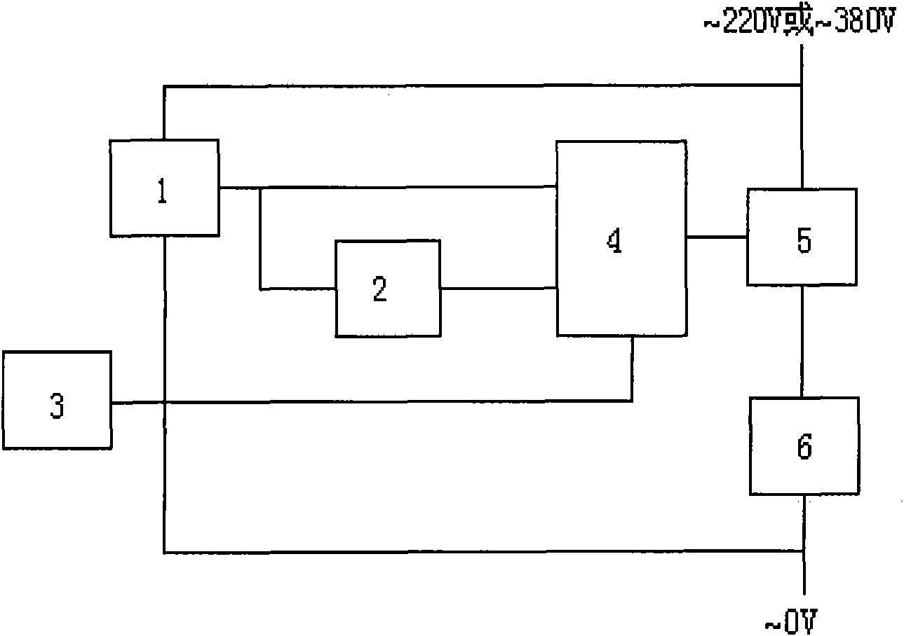
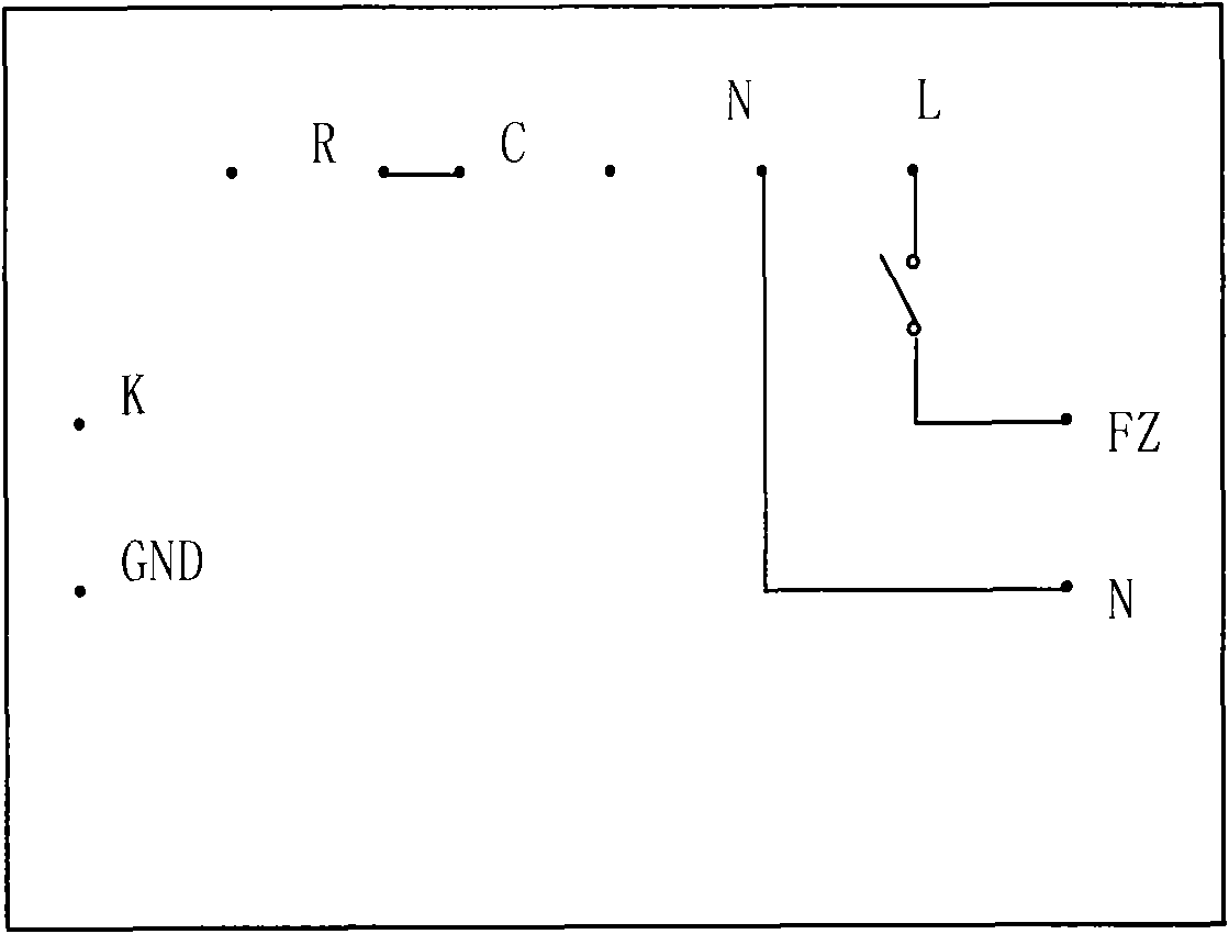
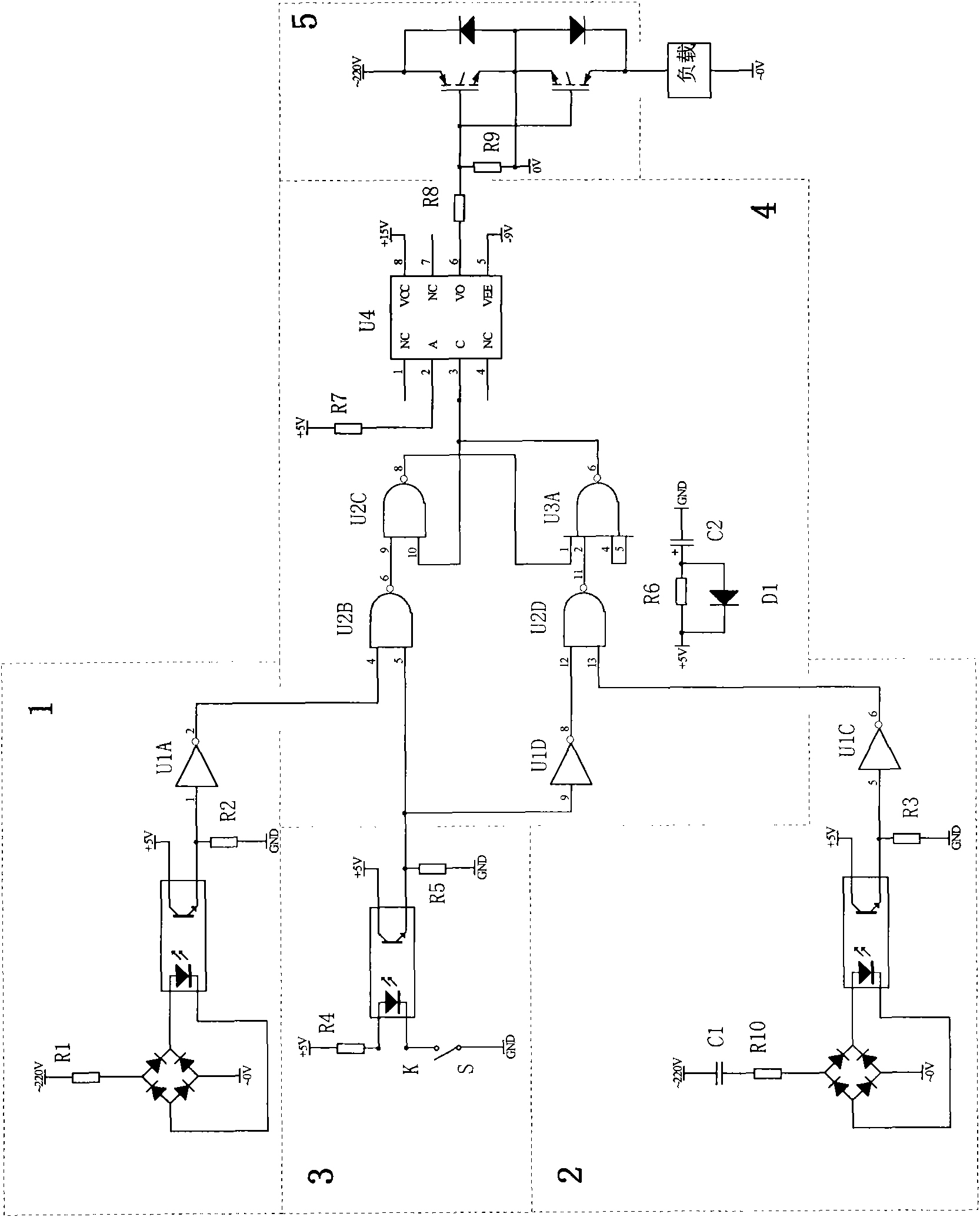
[0020] See figure 1 , figure 2 , image 3 , The zero-current turn-off solid state relay of the present invention includes a power supply voltage zero-crossing pulse generating circuit 1, a turn-off pulse generating circuit 2, an externally controlled switch signal circuit 3, a switch main control circuit 4, and a switch transistor circuit 5; the power supply voltage The output terminal of the zero-crossing pulse generating circuit is electrically connected to the voltage signal input terminal of the switch main control circuit, and the output terminal of the turn-off pulse generating circuit is electrically connected to the turn-off signal input terminal of the switch main control circuit, so The output terminal of the externally controlled switch signal circuit is electrically connected with the control signal input terminal of the switch main control circuit, and the control signal output terminal of the switch main control circuit is electrically connected with the input term...

Embodiment 2

[0029] Embodiment 2: This embodiment is an improved solution on the basis of Embodiment 1. For the technical features in this embodiment that are the same or similar to those of Embodiment 1, please refer to the disclosure of Embodiment 1 or the principle description for understanding , Should also be the content disclosed in this embodiment, and will not be repeated here.

[0030] See figure 1 , figure 2 , Figure 4 This embodiment discloses a time-delay type zero-current turn-off solid state relay. The turn-off pulse generation circuit in this embodiment is a time-delay pulse generation circuit. The turn-off pulse generation circuit has a monostable multiple Vibrator U5A (model 74LS123), pin 2 of the monostable multivibrator is electrically connected to the output terminal of the power supply voltage zero-crossing pulse generating circuit, and pin 4 of the monostable multivibrator is connected to a NAND gate Pin 1 of circuit U2A (model 74LS00) is electrically connected, pin 3 ...

Embodiment 3

[0032] This embodiment is an improved solution based on the first embodiment. The technical features in this embodiment are the same as or similar to those of the first embodiment. Please refer to the disclosed content or principle description of the first embodiment for understanding. The content disclosed in this embodiment will not be repeated here.

[0033] See figure 1 , figure 2 , image 3 with Figure 5 In this embodiment, the power supply voltage zero-crossing pulse generating circuit adopts Figure 5 The technical solution shown. There is a voltage comparator U1H (model LM339) in the power supply voltage zero-crossing pulse generating circuit of this embodiment. Pin 6 of the voltage comparator is connected to a voltage divider circuit, and pin 7 of the voltage comparator is connected to a resistor R24 ​​to the ground. The pin 1 of the comparator is connected to an output resistor R26, and connected to a +5V power supply through resistor 25, the output end of the output ...


PUM


Abstract

The invention relates to a zero-current switched-off solid state relay, which comprises a power voltage zero-crossing pulse generation circuit, a switching-off pulse generation circuit, an external control switch signal circuit, a switch master control circuit and a switch transistor circuit, wherein the output end of the power voltage zero-crossing pulse generation circuit is electrically connected with the voltage signal input end of the switch master control circuit; the output end of the switching-off pulse generation circuit is electrically connected with the switching-off signal input end of the switch master control circuit; the output end of the external control switch signal circuit is electrically connected with the control signal input end of the switch master control circuit; and the control signal output end of the switch master control circuit is electrically connected with the input end of the switch transistor circuit. The solid state relay can be switched on in the zero-crossing of a power voltage and switched off in the zero-crossing of a load current, avoids relatively more intensive impact to a switch at the moment of switching a circuit on and off, protects the switch and prolongs the service life of the switch.

Description

Technical field [0001] The invention relates to a zero-current turn-off solid-state relay. The solid-state relay includes a power supply voltage zero-crossing pulse generating circuit, a turn-off pulse generating circuit, an external control switch signal circuit, a switch main control circuit, and a switch transistor circuit. The solid state relay power supply Turns on when the voltage crosses zero, and turns off when the load current crosses zero. technical background [0002] Solid state relays (SSR), also known as solid state relays, are a new type of non-contact electronic switching device composed of electronic components developed by the combination of modern microelectronics technology and power electronic technology , It uses the switching characteristics of electronic components to achieve the purpose of making and breaking the circuit without contact and spark. The relay is a four-terminal device, including two input terminals and two output terminals. The input termi...

Claims


Application Information

Patent Timeline
Patent Type & Authority Applications(China)
IPC IPC(8): H03K17/567H03K17/785
Inventor 张玮张维平李裕宽赵勤
Owner 北京众智同辉科技有限公司
Why Eureka
Try Eureka