Voltage stabilization for grid-controlled x-ray tubes

一种X射线、控制电极的技术,应用在X射线设备、用于放射诊断的仪器、应用等方向,能够解决飞弧危险、危害、拍摄时间相互影响等问题,达到改善电压恒定、避免电压尖峰的效果

Active Publication Date: 2011-05-11
SIEMENS HEALTHCARE GMBH
View PDF9 Cites 8 Cited by
  • Summary
  • Abstract
  • Description
  • Claims
  • Application Information

AI Technical Summary

Problems solved by technology

Deviations of this actual tube voltage from the nominal value are quantitatively up to 40% and lead to non-monochromatic radiation at the start or end of the radiation and to an increased risk of arcing in the event of an overvoltage peak and the resulting arcing and other hazards
This leads to an interaction of the acquisition time in the beam quality and is therefore significant especially in the case of very short pulses

Method used


Image

  • Voltage stabilization for grid-controlled x-ray tubes
  • Voltage stabilization for grid-controlled x-ray tubes
  • Voltage stabilization for grid-controlled x-ray tubes

Examples


Embodiment Construction

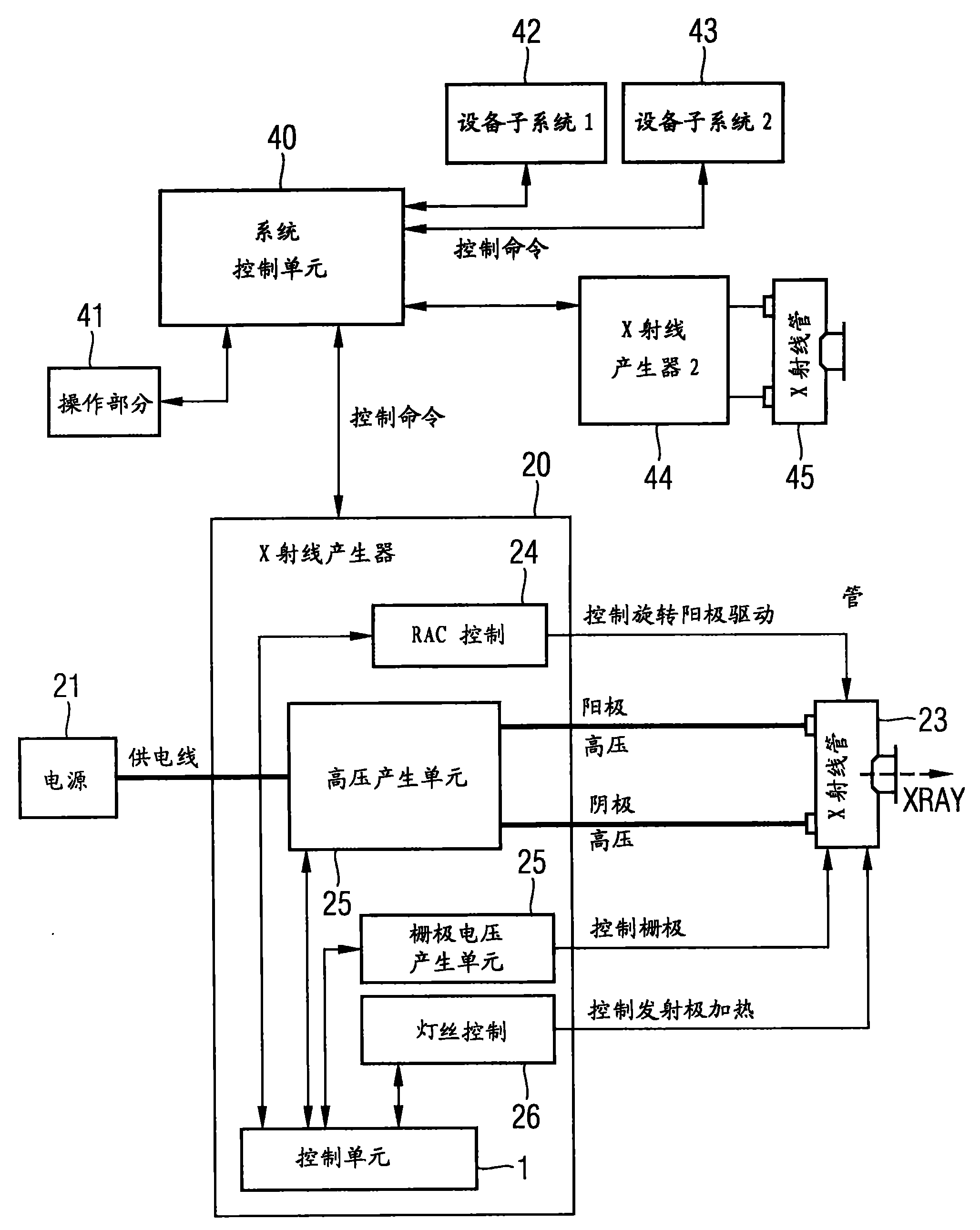
[0027] figure 1 A schematic diagram typical for current equipment is shown of the components of the X-ray tube. X-ray generator 20 includes control unit 1 and components: inverter / high voltage generator 22, anode drive 24 (RAC: Rotation Anode Control, rotating anode control), grid voltage generation unit 25 and for X-ray tube 23 Control unit 26 for cathode or emitter heating. Furthermore, a power supply 21 is also shown in the figure. By means of these elements, the required voltages (anode or cathode voltage and grid voltage) and other signals (control rotating anode drive, control emitter heating, . . . ) are provided for the X-ray tube 23 . X-rays XRAY are generated by means of an X-ray tube 23 . Furthermore, there is a central control unit 40 with an operating element 41 . The control of further devices 42 and 43 as well as of a second x-ray generator 44 , which drives a further x-ray tube 45 , is provided by means of the control unit 40 .

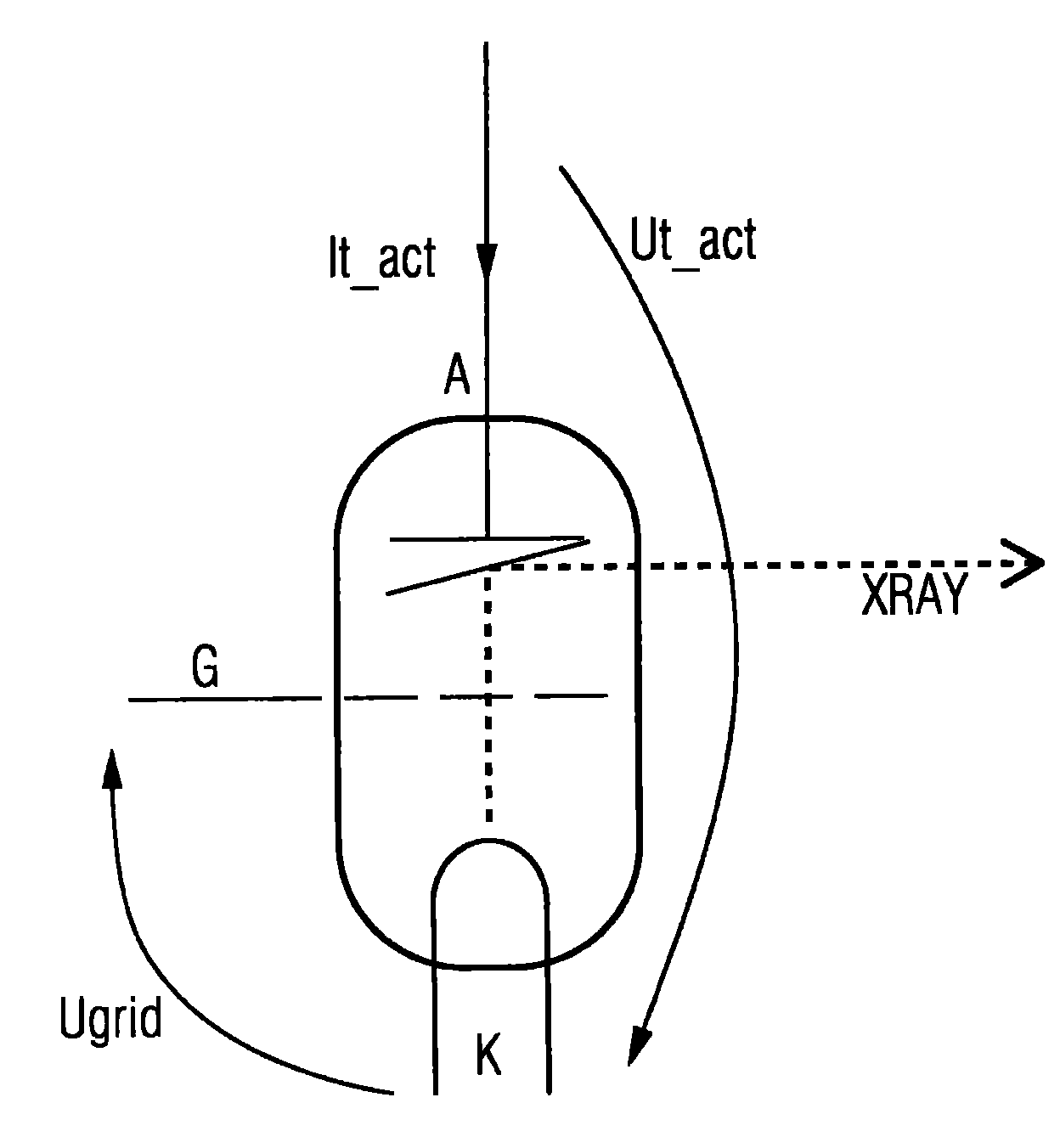
[0028] figure 2 An X-ray...


PUM


Abstract

The present embodiments improve the radiation monochromy of an x-ray device with a control electrode for controlling a flow of electrons generated between a cathode and an anode. A correction voltage is generated in accordance with a correction function. This correction voltage is used for correction of a voltage applied between the anode and the cathode in terms of a constant voltage, even in the period of control using the control electrode. The voltage applied between the anode and the cathode is corrected with the generated correction voltage.

Description

technical field [0001] The invention relates to an x-ray system having a control electrode for controlling the electron flow generated between a cathode and an anode and to a method for operating the x-ray system. Background technique [0002] X-rays are widely used in medical diagnosis. The generation of x-rays usually takes place here by means of so-called x-ray tubes. X-ray tubes generally include an envelope in which a vacuum is established. In addition, the tube is configured with an anode and a cathode located inside the vacuum envelope. For operation, the cathode is usually heated in order to support the emission of electrons. X-ray generation is then performed by applying a voltage between the anode and cathode. This is usually a high voltage in the range of 40-125 kV, which is provided by so-called x-ray generators (generators). The applied voltage causes electrons to come out of the cathode, be accelerated and when they hit the anode generate X-rays which exit...

Claims


Application Information

Patent Timeline
Patent Type & Authority Applications(China)
IPC IPC(8): H05G1/32A61B6/00
CPCH05G1/58
Inventor 约翰尼斯·沃尔克
Owner SIEMENS HEALTHCARE GMBH
Why Eureka
Try Eureka