Hydraulic/ultrasonic coupling cavitation device

An ultrasonic coupling and cavitation technology, applied in the field of cavitation, can solve the problem that the cavitation intensity of hydraulic cavitation is not as good as that of ultrasonic cavitation, and achieve the effect of improving efficiency and increasing cavitation intensity

Active Publication Date: 2011-05-18
GUANGZHOU NEWPOWER ULTRASONIC ELECTRONICS EQUIP +1
View PDF5 Cites 35 Cited by
  • Summary
  • Abstract
  • Description
  • Claims
  • Application Information

AI Technical Summary

Problems solved by technology

Compared with ultrasonic cavitation, hydraulic cavitation has simple equipment and low cost, and can generate large-scale cavitation fields (such as orifice plates, venturi tubes, vario

Method used


Image

  • Hydraulic/ultrasonic coupling cavitation device
  • Hydraulic/ultrasonic coupling cavitation device
  • Hydraulic/ultrasonic coupling cavitation device

Examples


Embodiment 1

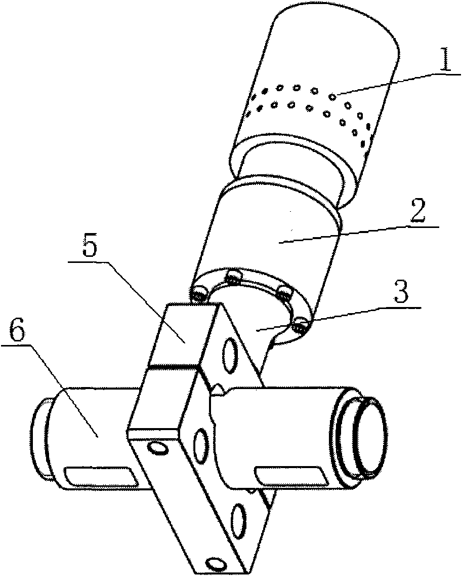
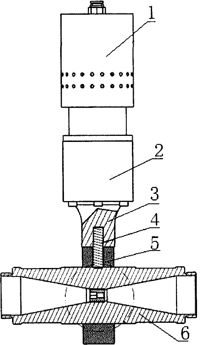
[0025] Hydraulic / ultrasonic coupled cavitation devices such as Figure 1~3 As shown, it includes a hydraulic cavitation mechanism and an ultrasonic functional mechanism, and an ultrasonic functional mechanism is installed on the hydraulic cavitation mechanism. The hydraulic cavitation mechanism can be a Venturi tube 6 . The ultrasonic functional mechanism includes an ultrasonic transducer 1, a connecting flange 2, a horn 3 and a functional fixture 5. The ultrasonic transducer 1 is connected to the horn 3 through the connecting flange 2, and the horn 3 is connected to the functional fixture 5. , the Venturi tube 6 is clamped by the functional clamp 3 . The connecting flange 2 is set on the node position. The functional fixture 5 is clamped at the liquid whistle or the lower part of the Venturi tube 6, through the organic combination of the piezoelectric ultrasonic cavitation and the hydraulic cavitation of the Venturi tube 6 itself, without interfering with each other, the ca...

Embodiment 2

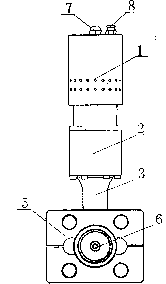
[0028] Hydraulic / ultrasonic coupled cavitation devices such as Figure 6~7 As shown, the orifice plate 9 is clamped in the functional fixture 5, and the holding point is located at or below the orifice plate. A close-hole flange is provided at the port of the orifice plate 9 for easy connection.

[0029] The ultrasonic transducer 1 mentioned above can be piezoelectric ceramic type or magnetostrictive type, its frequency band is: 10khz-130khz, single power: 5-5000w.


PUM


Abstract

The invention discloses a hydraulic/ultrasonic coupling cavitation device which comprises a hydraulic cavitation mechanism and an ultrasonic functional mechanism, wherein the ultrasonic functional mechanism is arranged on the hydraulic cavitation mechanism; the ultrasonic functional mechanism comprises an ultrasonic transducer, a connecting flange, an amplitude transformer and a functional fixture, wherein the ultrasonic transducer is connected with the amplitude transformer through the connecting flange, the amplitude transformer is connected with the functional fixture, and the hydraulic cavitation mechanism is arranged in the functional fixture and can be a Venturi tube, a pore plate or a liquid nozzle. The invention has the advantages that: an electric ultrasonic cavitation device is combined with the hydraulic cavitation device, and the coupling synergistic effect of the ultrasonic cavitation and the hydraulic cavitation can greatly enhance the cavitation effect to ensure that cavitation energy, sound pressure, sound intensity and efficiency are greatly improved. The hydraulic/ultrasonic coupling cavitation device can be effectively used in industrial production processes of sewage degradation treatment, oil water demulsification treatment, liquid inactivation treatment, Chinese medicine extraction, induced crystallization, wine ageing treatment, material uniform dispersing treatment, and the like.

Description

technical field [0001] The invention relates to the technical field of cavitation, and is a comprehensive, comprehensive and complementary hydraulic / ultrasonic coupling cavitation device that is simple in structure, can be used in large-scale production, and can realize cavitation functions. Background technique [0002] Cavitation refers to the formation, development and collapse of voids in a liquid and its subsequent dynamic behavior when the pressure of the liquid drops to a sufficiently low level. [0003] Studies have shown that: in the cavitation field, countless cavities are formed inside the liquid, and when the cavities collapse, instantaneous high temperature and high pressure are generated in the small space inside and around the cavities, and in the liquid around the cavities Form strong shock waves and high-speed micro jets. Therefore, the collapse of the cavitation will be accompanied by extremely complex physical and chemical effects, such as mechanical effe...

Claims


Application Information

Patent Timeline
IPC IPC(8): B01F13/10B01F11/02B01F5/02B01F3/04
Inventor 严卓晟严卓理卢小斌黄伟枢白立新李超邓京军
Owner GUANGZHOU NEWPOWER ULTRASONIC ELECTRONICS EQUIP
Why Eureka
Try Eureka