Feed-in mechanism for cold-rolling pipe mill

A technology of feeding mechanism and cold rolling mill, applied in metal rolling, metal rolling, metal processing equipment, etc. Conducive to manufacturing, concise overall structure, and helpful for installation

Inactive Publication Date: 2012-07-11
CHANGSHU MEILI MACHINERY MFG
View PDF9 Cites 3 Cited by
  • Summary
  • Abstract
  • Description
  • Claims
  • Application Information

AI Technical Summary

Problems solved by technology

However, there is no corresponding technical revelation in the published patents and non-patent literature, and there is no report of success in the industry.

Method used


Image

  • Feed-in mechanism for cold-rolling pipe mill
  • Feed-in mechanism for cold-rolling pipe mill
  • Feed-in mechanism for cold-rolling pipe mill

Examples


Embodiment Construction

[0015] In order to enable the examiners of the patent office, especially the public, to understand the technical essence and beneficial effects of the present invention more clearly, the applicant will describe in detail the following in the form of examples, but none of the descriptions to the examples is an explanation of the solutions of the present invention. Any equivalent transformation made according to the concept of the present invention which is merely formal but not substantive shall be regarded as the scope of the technical solution of the present invention.

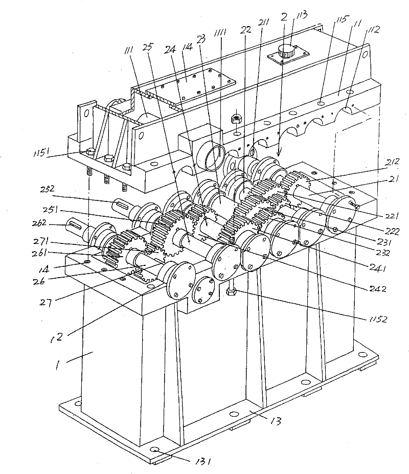
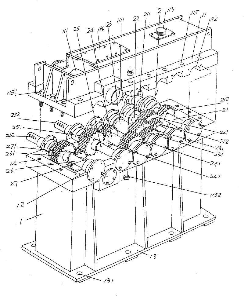
[0016] See figure 1 , provides the box seat 1 as the feeding mechanism of the cold rolling mill of the present invention, the box seat 1 is a hollow rectangular body, that is, the structure of a cuboid, and the box seat 1 is extended outwards from the peripheral edge of the bottom of the box seat 1 The fixing flange 13 is provided with mounting and fixing holes 131 at intervals on the fixing flange 13 of the ...


PUM


Abstract

The invention relates to a feed-in mechanism for a cold-rolling pipe mill, and belongs to the technical field of machining machines of metal pipes. The feed-in mechanism comprises a box base and a transmission speed reduction device, wherein a box cover is arranged on the upper part of the box base; and the transmission speed reduction device is arranged on the box base and is covered by the box cover. The feed-in mechanism is characterized in that: the transmission speed reduction device comprises a power input shaft, a first speed reduction shaft, a second speed reduction shaft, a third speed reduction shaft, a first power output shaft, a second power output shaft and a reversing shaft, which are arranged on the box base sequentially and rotationally, wherein the power input shaft is intransmission connection with an external power device and is matched with the first speed reduction shaft; the first speed reduction shaft is matched with the second speed reduction shaft; the secondspeed reduction shaft is matched with the third speed reduction shaft; the third speed reduction shaft is matched with the first power output shaft; the reversing shaft is positioned between the first power output shaft and the second power output shaft and is matched with the first power output shaft and the second power output shaft; and a core rod conduit for allowing a core rod to pass through is formed on the box cover. The feed-in mechanism has a simple integral structure, is favorable for manufacturing and contributes to installation and maintenance in the future.

Description

technical field [0001] The invention belongs to the technical field of metal pipe material processing machinery, and in particular relates to a feeding mechanism of a cold rolling pipe machine. Background technique [0002] Cold-rolled pipe mills are widely used in the pipe processing industry, and there is no shortage of technical solutions related to cold-rolled pipe mills in Chinese patent documents. For example, a two-roller cold-rolled pipe mill disclosed in the utility model patent authorization announcement number CN201223884Y Rolling mill tube billet continuous feeding device, the achievements of this program have solved the technical problem that the previous two-roll cold-rolled tube mill cannot work continuously, because, when the two-roll cold-rolled tube mill in the prior art is fed Finally, since the feeding trolley can only withstand the rear end of the tube billet, the feeding trolley must be returned to the original position (reset), and the next tube blank ...

Claims


Application Information

Patent Timeline
Patent Type & Authority Patents(China)
IPC IPC(8): B21B39/02
Inventor 朱平张其余陈东武薛志军吕斌
Owner CHANGSHU MEILI MACHINERY MFG
Why Eureka
Try Eureka