
Steel wire drawing and centering device for steam turbine assembly

A technology for steel wire drawing and steam turbines, which is applied in metal processing, metal processing equipment, manufacturing tools, etc., can solve problems such as processing difficulties, quality reduction in alignment, and heavy false shafts, etc., and achieve low processing accuracy requirements, save economic costs, and use The effect of looser conditions

Active Publication Date: 2011-05-18
SHANDONG QILU ELECTRIC MOTOR MFG
View PDF4 Cites 5 Cited by
  • Summary
  • Abstract
  • Description
  • Claims
  • Application Information

AI Technical Summary

Problems solved by technology

There are mainly the following problems in using the dummy shaft for centering: In order to avoid the quality of the dummy shaft being too long (steam turbines generally need to be more than 6 meters long) and the deformation caused by its own weight, the dummy shaft is generally made thicker. guarantee its rigidity
Therefore, the dummy shaft is generally cumbersome and wastes materials; because the coaxiality is guaranteed by radial equidistant when centering, the circumferential machining accuracy of the dummy shaft is high, the surface finish is high, and processing is difficult; in order to match the dummy shaft For use, both ends must have high-precision support, and each end needs a specially processed dummy bearing; it is time-consuming and laborious to adjust the position of the dummy shaft

Method used


Image

  • Steel wire drawing and centering device for steam turbine assembly
  • Steel wire drawing and centering device for steam turbine assembly
  • Steel wire drawing and centering device for steam turbine assembly

Examples


Embodiment Construction

[0020] The present invention will be further described below with reference to the accompanying drawings and embodiments.

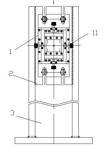
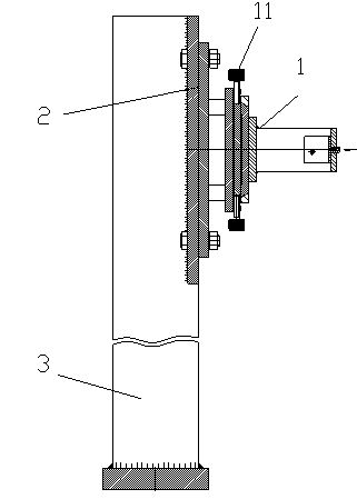
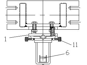
[0021] figure 1 , figure 2 , image 3 , Figure 4 , Figure 5 Among them, it includes a wire frame 1, and the wire frame 1 is installed on the support 3 through the support plate 2 of the wire frame; The device is connected, and a steel wire pull block 6 is provided on the steel wire fixing frame 5 .

[0022] The adjusting device comprises a pair of longitudinal first adjusting plates 7 arranged on both sides of the base plate 4 and a pair of horizontal second adjusting plates 8 distributed on the upper and lower sides of the base plate 4; There is a first side pressing plate 9, and second side pressing plates 10 are arranged on the outer sides of the two transverse second adjusting plates 8; an adjusting screw 11 is distributedly connected to each adjusting plate and each side pressing plate.

[0023] The adjusting screws 11 are respectively conne...


PUM


Abstract

The invention relates to a steel wire drawing and centering device for steam turbine assembly. The device has simple structure, is convenient to use and can adjust the steel wire more accurately. The device in the invention comprises a steel wire drawing frame, wherein the steel wire drawing frame is arranged on a support through a steel wire frame supporting plate and comprises a bottom plate; the bottom plate is provided with an adjusting device; a steel wire fixing frame is connected with the adjusting device; and the steel wire fixing frame is provided with a steel wire pulling block.

Description

[0001] technical field [0002] The invention relates to a steel wire centering device for assembling a steam turbine. Background technique [0003] As a high-temperature, high-pressure, and high-precision equipment, the steam turbine requires high positional accuracy of the impeller during its assembly process, so an auxiliary centering method is required. At present, the main centering method existing in China is the centering of the false shaft, that is, the false shaft is firstly aligned through the cylinder so that it is located in the center of the steam turbine cylinder. Then use it to center the newly installed impeller. There are mainly the following problems in using the dummy shaft to find the center: in order to avoid the quality of the dummy shaft being too long (the steam turbine generally needs to be more than 6 meters in length), and the quality of the alignment caused by the deformation caused by its own weight, the dummy shaft is generally made thicker. g...

Claims


Application Information

Patent Timeline
IPC IPC(8): B23P19/10
Inventor 王东光李青海李建华崔萍杨震宇王凯
Owner SHANDONG QILU ELECTRIC MOTOR MFG
Learn More