One-step forming process and die of carbon fiber driving shaft

A molding process and molding mold technology, which can be applied to household appliances, other household appliances, household components, etc., can solve the problems of time-consuming, labor-intensive, low torsional strength, and high production cost, and achieve simple mold structure and enhanced torsional strength , the effect of reducing the production cost

Active Publication Date: 2011-05-18
SHANDONG BENO COOLING EQUIP CO LTD
View PDF8 Cites 4 Cited by
  • Summary
  • Abstract
  • Description
  • Claims
  • Application Information

AI Technical Summary

Problems solved by technology

[0003] The purpose of the present invention is to provide a carbon fiber transmission shaft one-time molding process and mold to solve the complex structure of the processing mold in the prior art, high precision requirements, labor-intensive, time-consuming, and high production costs. Influenced by secondary molding, poor concentricity, low torsional strength, etc.

Method used


Image

  • One-step forming process and die of carbon fiber driving shaft
  • One-step forming process and die of carbon fiber driving shaft
  • One-step forming process and die of carbon fiber driving shaft

Examples


Embodiment Construction

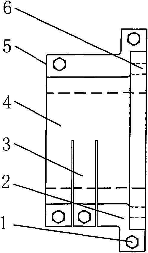
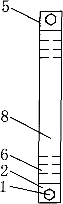
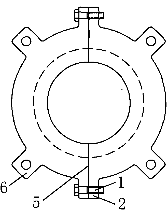
[0015] As shown in the figure; the one-time molding process of the carbon fiber transmission shaft flange of the present invention adopts a split mold, and the mold is composed of an inner mold 7 and an outer mold 4. Disc 2 snaps together and bolt 1 connects. The inner end of the outer mold 4 is a disc structure, the outer is a sleeve structure, the center line parting cut, the flange plate 2 is fastened, and the bolt 1 is connected; the sleeve part of the outer mold is cut transversely along one parting surface to form a compaction Card strip 3. A certain gap is processed at the position corresponding to the clamping strip 3 and the parting surface so as to tighten the mandrel by bolts, and the mandrel is identical in structure with the prior art. Fastening lugs 6 are correspondingly arranged on the discs of the inner mold 8 and the outer mold 4 , and the center of the fastening lugs 6 is provided with a bolt hole 7 . The above-mentioned mold can be used to form a carbon fi...


PUM


Abstract

The invention discloses one-step forming process and die of a carbon fiber driving shaft. An inner die is in a disk type structure, is partitioned and cut along a center line, is buckled in a flange type and is connected by a bolt. The inner end of an outer die is in a disk structure; the outside of the outer die is in a sleeve structure; and the outer die is portioned and cut along a center line, is buckled in a flange type and is connected by a bolt. The sleeve part of the outer die is transversely cut along a partition surface on one side to form a compressed clamping strip so as to be convenient for fastening a mandrel. Fastening lug seats are correspondingly arranged on the inner die disk and the outer die disk and are provided with bolt holes. The one-step forming process comprises the steps of 1. preparation of the carbon fiber driving shaft, 2.flange preparation, and 3, ring flange shaping. In the invention, the ring flange processing die has simple structure, is simple, convenient andfeasible for production process and is convenient and quick for processing and using; the one-step forming of the carbon fiber driving shaft and the flange can be realized and the production cost of the die and products can be reduced; the produced carbon fiber driving shaft has high concentricity; the continue track of secondary forming can be eliminated; the torsion strength of the flange of the carbon fiber driving shaft can be enhanced; and the production efficiency and the quality of products can be improved.

Description

technical field [0001] The invention belongs to the technical field of composite material production, and relates to a carbon fiber transmission shaft processing and forming technology. Background technique [0002] At present, carbon fiber transmission shafts are produced at home and abroad, and flanges and shaft tubes are made separately, and then bonded into one secondary molding process. It is time-consuming and labor-intensive, which increases the production cost. The carbon fiber transmission shaft produced is affected by the secondary bonding molding, has poor concentricity and low torsional strength. Contents of the invention [0003] The purpose of the present invention is to provide a carbon fiber transmission shaft one-time molding process and mold to solve the complex structure of the processing mold in the prior art, high precision requirements, labor-intensive, time-consuming, and high production costs. The impact of secondary molding, poor concentricity, lo...

Claims


Application Information

Patent Timeline
Patent Type & Authority Applications(China)
IPC IPC(8): B29C69/02B29C33/00B29L31/00
Inventor 李金鹏
Owner SHANDONG BENO COOLING EQUIP CO LTD
Why Eureka
Try Eureka