Computer binocular vision denture scanning device and three-dimensional reconstruction method thereof

A technology of binocular vision and scanning device, applied in the field of denture scanning, can solve the problems of high cost, complex grating projection device and high maintenance cost

Inactive Publication Date: 2011-05-18
SHENYANG INST OF AUTOMATION - CHINESE ACAD OF SCI
View PDF0 Cites 54 Cited by
  • Summary
  • Abstract
  • Description
  • Claims
  • Application Information

AI Technical Summary

Problems solved by technology

At present, denture scanning equipment using non-contact computer vision three-dimensional measurement technology mainly adopts two methods. One is to project a surface grating onto the surface of the denture when measuring the denture, and a CCD camera captures the image to extract three-dimensional points on the denture surface. The data is sampled, neither the denture nor the camera moves during the measurement, this method requires a complex raster projecti

Method used


Image

  • Computer binocular vision denture scanning device and three-dimensional reconstruction method thereof
  • Computer binocular vision denture scanning device and three-dimensional reconstruction method thereof
  • Computer binocular vision denture scanning device and three-dimensional reconstruction method thereof

Examples


Embodiment Construction

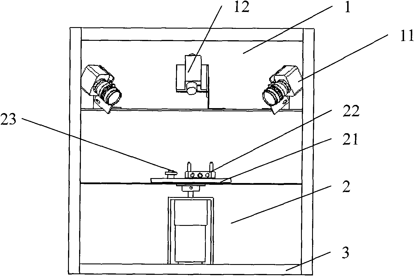
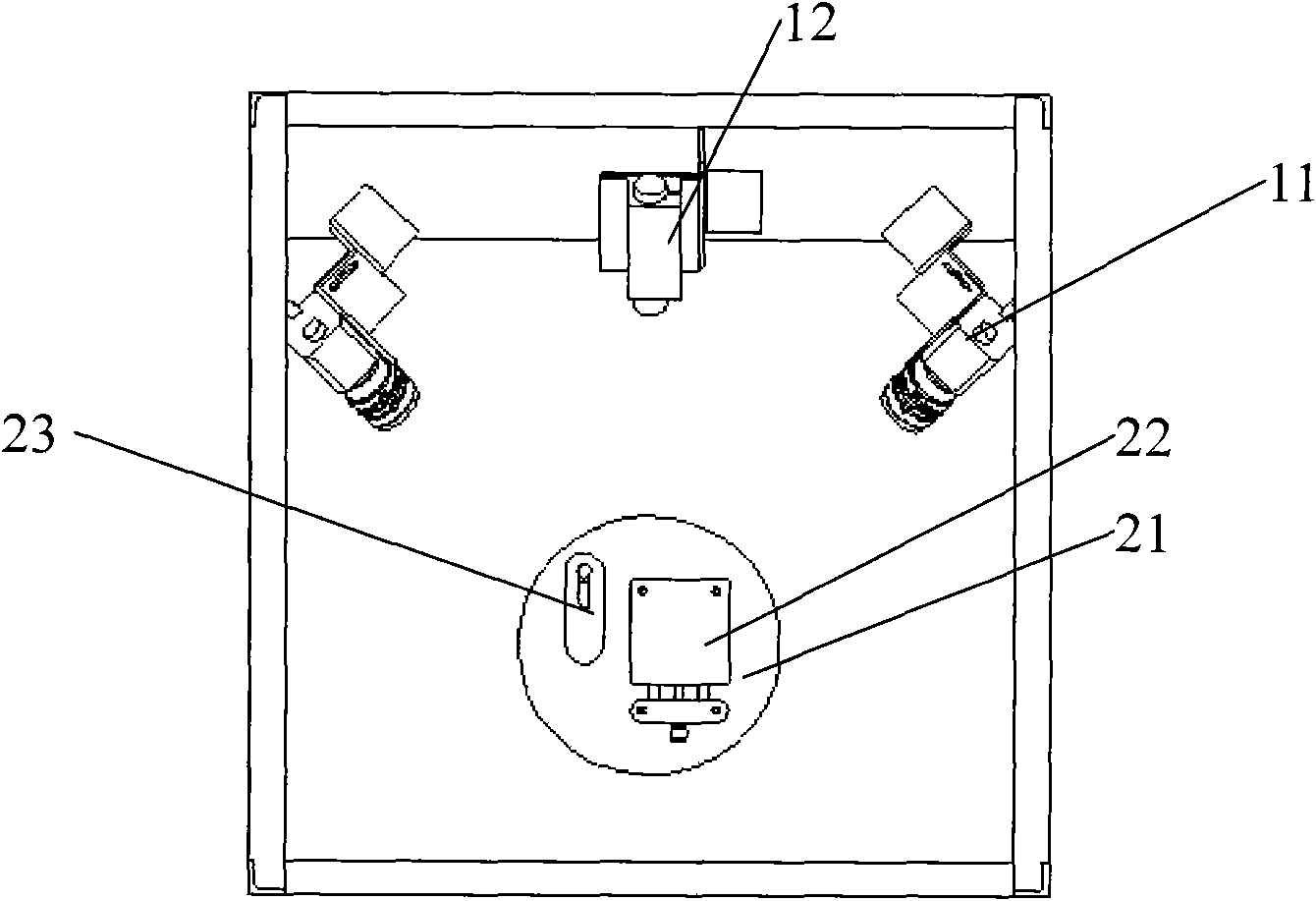
[0045] The device of the present invention is a measurement device integrating optical, mechanical and electrical technologies, such as Figure 1~4 As shown, the device includes:

[0046] Line-structured light vision collection part 1, rotating measuring table and its control part 2, and box body 3, wherein: line-structured light vision collection part 1 includes two high-resolution digital CCD cameras 11, one line-structured light laser 12, two The high-resolution digital CCD camera 11 is located above the center side of the rotating measuring platform and its control part 2, and is distributed symmetrically with the line structured light laser 12 as the center;

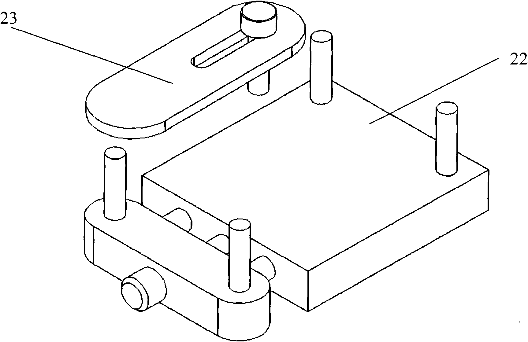
[0047] The rotating measuring table and its control part 2 include a rotating measuring table 21 and its driving mechanism and the first and second accessories 22 and 23. The first and second accessories 22 and 23 are arranged on the rotating measuring table 21. On the platform where the denture dental model is pla...


PUM


Abstract

The invention relates to a computer binocular vision denture scanning device and a three-dimensional reconstruction method thereof. The device comprises a linearly structured light vision collection part, a rotary measuring bed, a control part of the rotary measuring bed, and a box, wherein two high resolution digital charge coupled device (CCD) cameras are positioned on the central sides above the rotary measuring bed and the control part of the rotary measuring bed and symmetrically distributed by taking the linearly structured light laser as the centre in the linearly structured light vision collection part; first and second accessories in the rotary measuring bed and the control part of the rotary measuring part are arranged on the rotary measuring bed; the rotary measuring bed is driven by a driving mechanism to rotate; and the structures are arranged in the box. The method comprises: placing a denture on the rotary measuring bed; allowing the linearly structured light laser to project laser on the denture; driving the rotary measuring bed to rotate continuously by the driving mechanism; and taking pictures by two CCD cameras and transmitting the pictures to an external control computer to process the pictures to obtain three-dimensional data on the denture surface. In the invention, the mechanical structure and the control method need no various speed control, have no requirement on precision of spindle rotation of a motor, and are convenient to operate and high in scanning precision.

Description

technical field [0001] The invention relates to denture scanning technology in the technical field of measurement and testing, in particular to a computer binocular vision denture scanning device and a three-dimensional reconstruction method thereof. Background technique [0002] The development of computer vision technology provides strong technical support for the application of non-contact three-dimensional measurement technology in reverse engineering, industrial inspection and quality control. At the same time, the increasingly wide application in these fields also promotes the development of visual three-dimensional measurement technology . Such as structured light measuring instrument, triangulation method using line laser or spectral laser. Computer vision measurement technology has been widely used in denture scanning equipment due to its convenience, speed and accuracy. At present, denture scanning equipment using non-contact computer vision three-dimensional mea...

Claims


Application Information

Patent Timeline
IPC IPC(8): G01B11/25
Inventor 赵吉宾刘伟军夏仁波于彦凤付生鹏
Owner SHENYANG INST OF AUTOMATION - CHINESE ACAD OF SCI
Why Eureka
Try Eureka