

Deflecting optical wedge scanning device
An optical wedge scanning and optical wedge technology, used in optics, optical components, instruments, etc., can solve problems such as affecting adjustment accuracy, and achieve the effect of improving working environment, improving feed accuracy and working performance, and overcoming friction and abnormal noise.
Inactive Publication Date: 2011-05-18
TONGJI UNIV
View PDF13 Cites 14 Cited by
- Summary
- Abstract
- Description
- Claims
- Application Information
AI Technical Summary
Problems solved by technology
At the same time, in the prior art, the motor screw slides along the V-shaped groove at the lower end of the frame, causing friction and noise, which affects the adjustment accuracy
Method used
View moreImage
Smart ImageViewing Examples

Examples
example
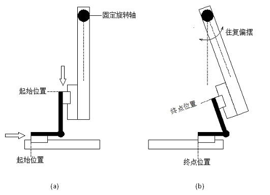
[0081] Example: When X=50mm, a=144mm, b=525mm, the values of Y and θ can be calculated respectively
[0082] mm
[0083]
[0084] 2. Knowing the rotation angle θ of the optical wedge, find the feed amount X of the horizontal slider and the displacement Y of the vertical slider
[0085] Draw a vertical line B'C through point B' and intersect AA'' at point C
[0086]
[0087]
[0088]
[0089] Example: When θ=10°, a=144, b=525, the values of X and Y can be calculated respectively
[0090]
[0091] .
Login to View More PUM
 Abstract
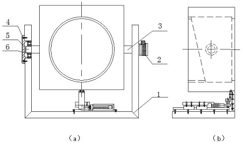
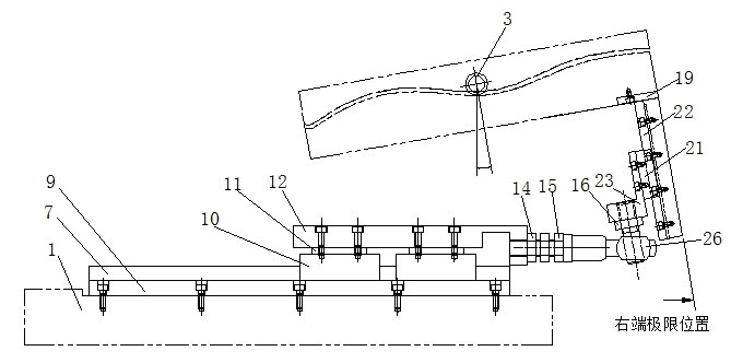
The invention relates to a deflecting optical wedge scanning device. The device comprises an optical wedge and picture frame assembly, an angle encoder, a horizontal rotating shaft, a working table and a driving control system, wherein the optical wedge and picture frame assembly consists of a wedged cushion block, an optical wedge, an elastic block, an optical wedge pressing plate, a picture frame and an O-shaped washer; the horizontal rotating shaft is divided into a left section and a right section which are positioned on the two sides of the picture frame respectively; the right end of the right section of the horizontal rotating shaft is fixed with the angle encoder; a first module consists of a linear motor, a horizontal guide rail, a horizontal slide block, a horizontal connecting block, a cover plate and a grating ruler; a second module consists of a double end threaded stud, a joint bearing and a single end threaded stud; a third module consists of a vertical guide rail, a vertical slide block, a picture frame connecting plate and an L-shaped plate; and the driving control system consists of a computer, an input / output control circuit, a step motor driver and a signal processing and control circuit, and can realize open loop or closed loop control. In the device, small-angle precise swinging of the optical wedge device is realized through traction of the slide block, so the motion control accuracy is improved. The device can be individually used or two devices can be combined for use, so the requirements of scanning and positioning in different directions can be met.
Description
technical field [0001] The invention relates to a deflection optical wedge scanning device. Background technique [0002] In the field of precision engineering, optical wedge components are widely used in various beam redirection propagation and optical path compensation, especially in optical dynamic scanning and alignment optical paths, often through the continuous rotation and yaw motion of the optical wedge to achieve high precision of the beam position. [0003] In the mechanical method of scanning and aligning beams at variable angles, how to achieve precise control of variable angles is a difficult problem in system design, especially in dynamic angle adjustments, which usually require opto-mechanical coordination to achieve desired adjustments. [0004] Commonly used methods to achieve yaw movement are: [0005] (1) The yaw movement of the device is realized by the method of jacking one end of the yaw device through the cam mechanism, prior technology (Liu Feng et ...
Claims
Login to View More Application Information
Patent Timeline
 IPC IPC(8): G02B26/10
Inventor李安虎李志忠姜旭春
OwnerTONGJI UNIV